

AGIBOT A3 Ultra User Manual
Welcome
Thank you for choosing the AGIBOT A3 Ultra Robot.
This user manual helps you fully understand and quickly get started with the AGIBOT A3 Ultra Robot (hereinafter referred to as "the Robot"), and provides detailed information on operation and maintenance to ensure an optimal user experience. Should you have any problems during use, please call our service hotline or contact our official WeChat account. Our professional technical support team will be glad to assist you.
Read User Manual: https://agirobot.feishu.cn/wiki/PcrowWlvvi35rMkVwOfc3y3En1B

Contact After-sales Service: /DOCS/OS/a3/after-sales
1. Important Notice
1.1 Safety Precautions
1. Know the Product: Before using the Robot for the first time, please read the manual to fully understand its functions, operating procedures, and all safety instructions.
2. Environmental Requirements: Operate the robot only on flat, dry and stable surfaces. Do not use it in environments with extreme high or low temperatures, high humidity, steep slopes, sharp drops, fragile ground or strong vibration.
3. Regular Inspection and Maintenance: Conduct regular maintenance and status checks on the Robot, focusing on key components such as joints, sensors, and the power system, to ensure the equipment remains in good working condition and to prevent safety hazards caused by component aging or damage.
4. Know the Emergency Stop Operations: Before use, familiarize yourself with the emergency stop operation method to halt the robot promptly in case of emergencies. Once the emergency stop is activated, all robot joints will lose support and collapse. For this reason, strictly observe on-site safety regulations and keep the protective frame in place at all times after an emergency stop. Do not activate the emergency stop unless necessary.
5. Reserve Operating Space: Before operation, ensure sufficient surrounding space for the robot to move. Do not use it in overly narrow areas or spaces crowded with people and obstacles, to prevent collision and pinching risks.
6. Electrical Safety: Before power-on, inspect cables, plugs and sockets to confirm they are intact and free of abnormalities. If a short circuit, overheating or other faults are detected, cut off the power supply immediately.
7. Prohibit Improper Use: Use the robot only in compliant and proper application scenarios. Do not operate it for dangerous, illegal or unauthorized purposes.
8. Confirm the Parking Location: Before entering the operating area, personnel must ensure that the robot is parked on level ground. Do not approach the robot while it is on a slope.
9. Restart after Shutdown: After shutting down, wait at least 30 seconds before powering the robot back on.
1.2 Safety Guidelines
1. Pre-Operation Checks
• a. Before powering on the robot or initiating any movement, ensure no personnel, debris or obstacles remain in the working area, especially around robotic arms, joints and other moving parts, to prevent collisions and personal injury.
• b. Operators shall inspect the robot for normal status before startup and confirm the completion of system self-check.
2. Standardized Operation and Training Requirements
All operating personnel must receive operating training in advance. Operators shall be familiar with the robot’s specifications, standard operating procedures and exception handling protocols, to avoid safety risks arising from improper operation.
3. Maintain a Safe Distance
Keep a minimum 1 meter safe distance from the robot’s working area during operation to prevent collision hazards caused by sudden equipment movement. Do not stay within the robot’s predicted motion path, especially during high-speed operation.
4. Prohibition of Manual Intervention During Operation
Do not manually interfere with the robot while it is running. If adjustment, maintenance or manual handling is required, confirm the robot has come to a complete stop and is fully powered off before any operation.
5. Load and Component Usage Requirements
• a. Operate the robot within its rated load capacity. Do not apply loads exceeding its designed specification limits.
• b. When using end-effectors, grippers and other functional components, ensure full compatibility with the target workpiece. Mismatched components may cause extrusion, abnormal stress or permanent part damage.
6. Shutdown Procedures for Abnormal Conditions
In the event of abnormalities, malfunctions or unexpected faults, immediately activate emergency shutdown via the remote control to stop all robot motions without delay.
8. Remote Control Precautions
• a. If the robot is equipped with remote control functions, operate it only under stable and secure network conditions. Network interruptions, latency or external intrusion will impair control stability.
• b. Remote operators shall adopt real-time monitoring measures to continuously keep track of the robot’s running status and on-site environment, so as to ensure the safety of remote operation.
2. AGIBOT A3 Ultra Overview
2.1 Unpacking List
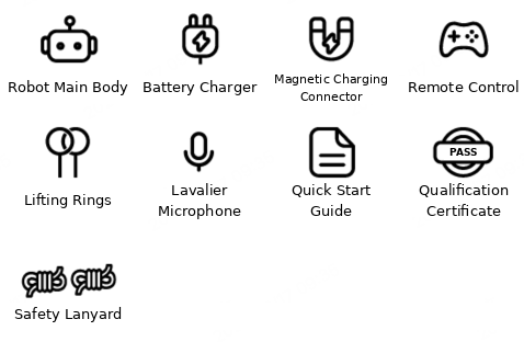
No. | Component Name | Quantity |
1 | Robot Main Body(incl two battery packs) | 1 |
2 | Battery Charger | 1 |
3 | Magnetic Charging Connector | 1 |
4 | Remote Control | 1 |
5 | Lavalier Microphone | 1 |
6 | Quick Start Guide | 1 |
7 | Qualification Certificate | 1 |
8 | Safety Lanyard | 2 |
9 | Lifting Rings | 2 |
2.2 Product Introduction
The AGIBOT A3 series products feature 31 to 71 degrees of freedom (varies by model and configuration), enabling flexible movement and high-precision posture control. The following details the specific configuration and feature highlights of the AGIBOT A3 Ultra.
• AGIBOT A3 Ultra: 2 degrees of freedom in the neck, 7 per arm, 3 in the waist, and 6 per leg. It is equipped with dexterous hands (standard 10-DOF dexterous hands, compatible with multiple dexterous hand models; the number of degrees of freedom varies by model).
• The perception system is equipped with front-view RGB stereo cameras, surround-view triple fisheye cameras, LiDAR, GPS RTK, UWB positioning, shoulder touch sensors, a chest RGB-D camera, and a hip RGB-D camera.
• The communication system is equipped with Wi-Fi, 4G/5G mobile network, and Bluetooth.
• The interaction system is equipped with omnidirectional microphones, speakers, a curved display, and omnidirectional indicator lights.
• The power system is equipped with a 1152Wh battery, providing a total battery life of 8 hours, including 4 hours of standing operation and over 4 hours of continuous walking. It supports direct charging, battery changing, with a charging time of ≤2 hours.
2.2.1 Component Names and Descriptions
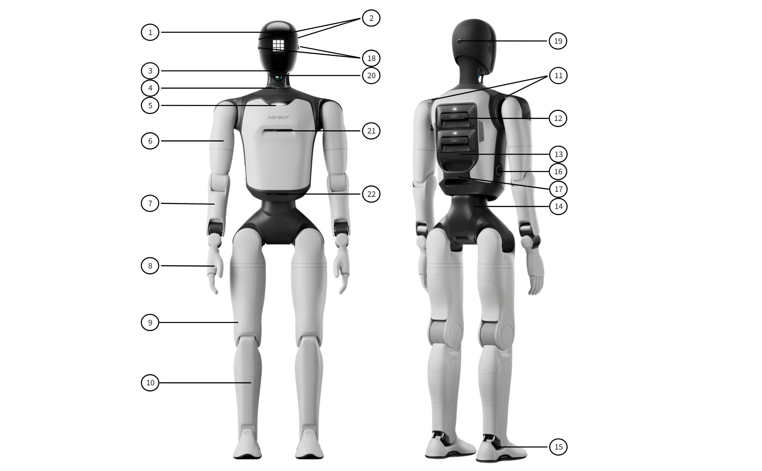
No. | Component | No. | Component | No. | Component |
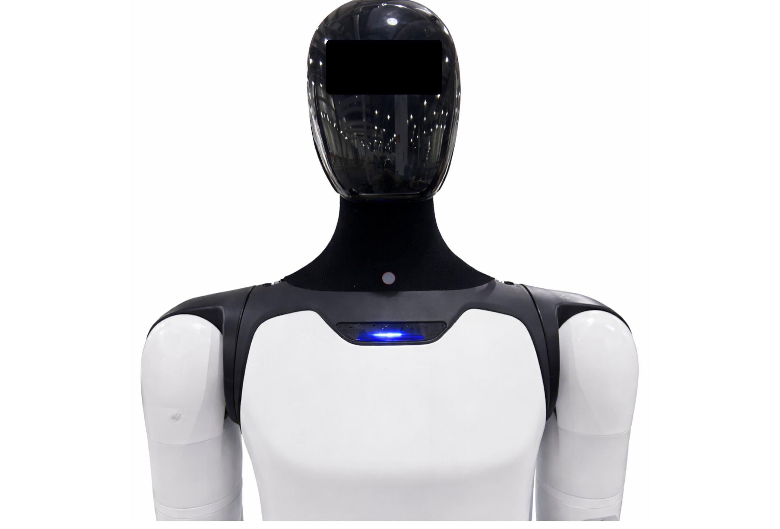
1 | Head Display | 9 | Thigh | 17 | Waist Handle |
2 | Left and Right Speakers | 10 | Calf | 18 | Left and Right Fisheye Cameras |
3 | Interactive Binocular Camera | 11 | Dual Shoulder Touch Sensors | 19 | Rear-View Fisheye Camera |
4 | Switch | 12 | Dual Battery Compartments | 20 | LiDAR |
5 | Microphone | 13 | Maintenance Bay | 21 | Chest RGB-D Camera |
6 | Upper Arm | 14 | Waist | 22 | Hip RGB-D Camera |
7 | Forearm | 15 | Foot | ||
8 | Dexterous Hand | 16 | Charging Port |
2.2.2 Robot Indicator Lights
The robot displays its current status through the head screen expressions, the chest light, and the ear lights. The chest light mainly indicates the robot’s operating, battery and fault status; the ear lights mainly indicate real-time interaction states such as listening and speaking.
Category | Status | Description | Light Effect |
Chest Light – Daily Status
| Resting | When the robot is lifted up and no other status is triggered | Light off |
Standby | The robot is powered on and waiting for user operation | Solid white | |
Charging | The robot is charging and not yet fully charged | Breathing white | |
Working | The robot is performing tasks such as navigation, guiding, delivery, dancing, or combat | Solid white | |
Voice Interaction | Listening | The robot is receiving the user’s voice | Flowing white |
Speaking | The robot is performing voice interaction tasks such as conversation, guiding, or skill expression. Note: non-voice-interaction scenarios such as dancing, system announcements, and audio announcements triggered from the client do not trigger this light effect
| Flowing white | |
Reminders and Faults | Find Robot | The user is locating the robot via the client | Red strobe (300 ms) |
Critical Fault
| A critical fault has occurred. Stop using the robot immediately and inspect it according to the system prompts | Solid red | |
Device Locked | The robot has entered the locked state | ||
Emergency Stop | Manual intervention for an out-of-control or dangerous situation of the robot | ||
Fault | A fault has occurred and must be handled according to the system prompts | Does not affect the light effect
| |
Warning | A condition requiring attention has occurred; for example, when one battery is removed, the robot displays the warning light effect | ||
Low Battery | When the combined level of "both batteries" drops to 30% or below, recharge or replace the batteries promptly | Solid white | |
Extremely Low Battery | When the combined level of "both batteries" drops to 10% or below, recharge or replace the batteries promptly | Solid red
|
2.2.3 Battery Indicator
Note: When using battery power, closely monitor the battery level. Low or nearly depleted batteries may cause the robot to topple suddenly due to insufficient output power. Recharge or replace the battery immediately when only one indicator remains, to maintain stable operation and avoid personal injury caused by the robot falling.
2.2.3.1 Location of Battery Indicator Lights
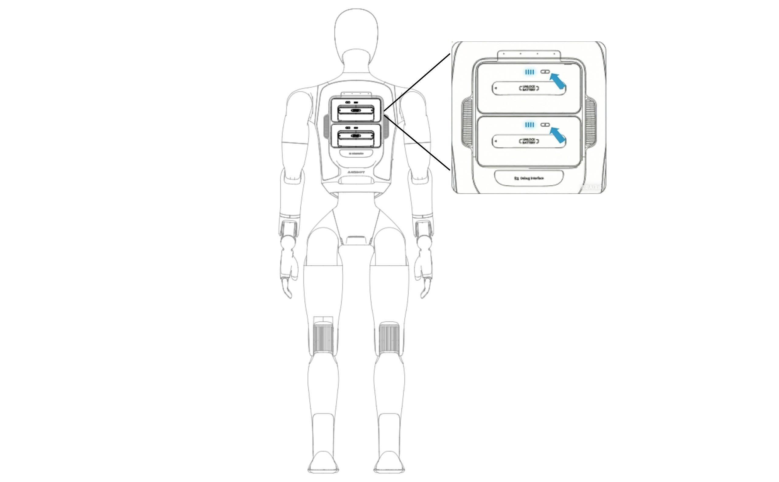
2.2.3.2 Indicator Status Description (Working)
Battery Light Status (Working) | Battery Level | Status Description |
All LEDs off | 0% | No power |
LED1 on, LEDs 2-4 off | 1% ≤ Battery Level < 25% | Critical Low Power (Recharge Immediately) |
LEDs 1-2 on, LEDs 3-4 off | 25% ≤ Battery Level < 50% | Low Power |
LEDs 1-3 on, LED4 off | 50% ≤ Battery Level < 75% | Sufficient power |
LEDs 1-4 on | 75% ≤ Battery Level < 100% | Full power |
2.2.3.3 Indicator Status Description (Charging)
Battery Light Status (Charging) | Battery Level | Status Description |
LED1 breathing, LEDs 2-4 off | Battery Level < 25% | Critical Low Power |
LED1 on, LED2 breathing, LEDs 3-4 off | 25% ≤ Battery Level < 50% | Low Power: Do not disconnect |
LEDs 1-2 on, LED3 breathing, LED4 off | 50% ≤ Battery Level < 75% | Medium Power: Operable; charging to full recommended |
LEDs 1-3 on, LED4 breathing | 75% ≤ Battery Level < 100% | Sufficient Power: Operable |
LEDs 1-4 on | Battery Level = 100% | Charging Complete: Power can be disconnected |
2.2.4 User Debugging Interfaces
No. | Hardware Expansion Interface | Interface | Description |
1 | Maintenance bay: for debugging and secondary development (waist) | USB Type-A 2.0 | Supports ADU/MDU serial port reading and debugging |
2 | Maintenance bay: for debugging and secondary development (waist) | Ethernet | Supports ADU debugging and secondary development |
3 | Maintenance bay: power interface (waist) | USB Type-C | 5 V/3 A output; can charge external devices such as the remote controller |
4 | Maintenance bay: for debugging and secondary development (head) | USB Type-C | Supports debugging and secondary development of the head HDU (RK3588s); supports connecting a microphone receiver |
2.3 Robot Joint Motion Range
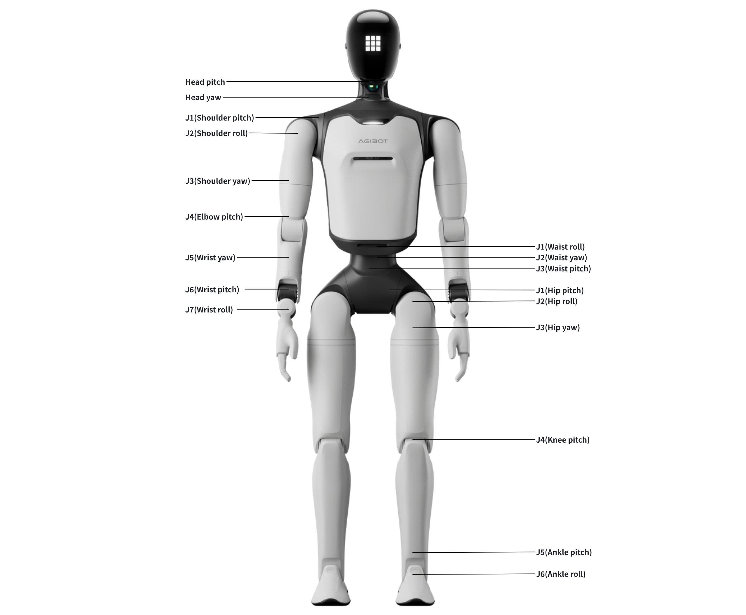
Joint Name | Joint Limit | Joint Name | Joint Limit |
Arm
| J1(Shoulder pitch): -165°~165° | Waist | J1(Waist roll): ±20° |
J2(Shoulder roll): -5°~150° | J2(Waist yaw): ±150° | ||
J3(Shoulder yaw): ±160° | J3(Waist pitch): -28°~24° | ||
J4(Elbow pitch):-55°~100° | Leg
| J1(Hip pitch): -144°~168° | |
J5(Wrist roll): ±160° | J2(Hip roll): -30~85° | ||
J6(Wrist pitch): ±93° | J3(Hip yaw): ±156° | ||
J7(Wrist yaw): ±93° | J4(Knee pitch): -7°~145° | ||
Head | Tilt joint (Head pitch): 15° (down), 25° (up) | J5(Ankle pitch): -52°~30° | |
Rotation joint (Head yaw): ±60° | J6(Ankle roll): ±20° |
Note: Joint limits are calculated based on structural design parameters. Individual differences may exist between devices, and these data are for reference only.
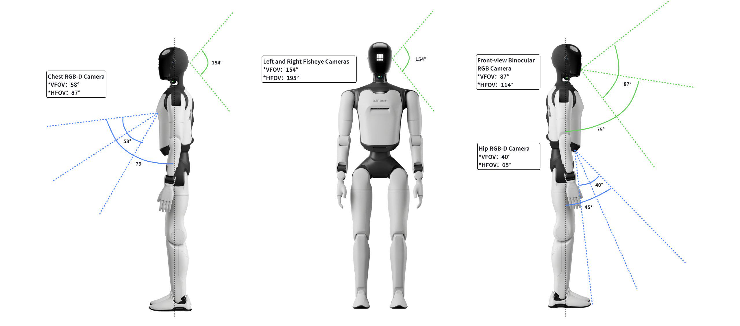
2.4 Robot Sensor Field of View
Robot Model | Perception Configuration | Capability |
AGIBOT A3 Ultra | Interactive Binocular Camera | Supports visual recognition and response in human-robot interaction scenarios |
Left and Right Fisheye Cameras | Surround-view environment perception, object recognition and obstacle avoidance | |
Rear-View Fisheye Camera | ||
Chest RGB-D Camera | Depth and image perception of the working area | |
Hip RGB-D Camera | Depth and image perception of the ground area |
2.5 Robot Specifications
Robot Model | AGIBOT A3 Ultra | |
Main Body | Height | 1.74 m |
Dimensions | 174 cm (H) x 52 cm (W) x 30 cm (L) | |
Weight | 60 KG | |
Active Degrees of Freedom | 51–71 | |
Neck Degrees of Freedom | 2 | |
Single Arm Degrees of Freedom | 7 | |
Waist Degrees of Freedom | 3 | |
Single Leg Degrees of Freedom | 6 | |
Dexterous Hand Degrees of Freedom | 10 (optional, up to 20 DOF) | |
Perception System | 3D LiDAR | Equipped |
Embodied Operation RGB-D Camera | Equipped | |
Terrain Perception RGB-D Camera | Equipped | |
Interactive RGB Camera | RGB Binocular Camera | |
Panoramic RGB Camera | Equipped | |
GPS | Equipped | |
GPS RTK | Equipped | |
UWB Positioning | Equipped | |
Shoulder Touch Sensors | Equipped | |
Communication | Communication Methods | WiFi, 4G/5G Network, Bluetooth |
Interaction | Microphone | Omnidirectional Microphone; Front and Rear 8-Microphone Array |
Speaker | Equipped | |
Face Screen | Curved Screen | |
Indicator Lights | Omnidirectional Indicator Lights | |
Performance | Knee Joint Peak Torque | 320 N·m |
Movement Speed | Max Daily Walking Speed: 1.8 m/s; Normal Daily Walking Speed: < 1.2 m/s; Maximum Laboratory Speed: 2.5 m/s; Max Running Speed: 5 m/s | |
Single Arm Payload | Rated 1 kg; extreme 5 kg | |
Operating Environment | Operating Temperature | -10°C to +45°C |
Power and Energy | Battery Capacity | 1152 W·h |
Battery Life | Total 8 h. * Actual battery life depends on usage and is affected by walking speed and load; standing / walking ratio = 1:1 | |
Charging Methods | Supports direct charging, battery swapping, and autonomous charging | |
Charging Time | ≤2 h | |
Charging Input Voltage | 110-220 V | |
Computing Power | Basic Computing Board | RK3588 * 2 |
Advanced Computing Board | NVIDIA Thor | |
Others | Handheld Wireless Terminal | Equipped |
Smart OTA Update | Equipped | |
Further Development | Supported |
2.6 Radio Frequency Specifications
Wi-Fi and Bluetooth
• 2.4 GHz Wi-Fi: 20 dBm (EIRP)
• Bluetooth: 20 dBm (EIRP)
• 5 GHz Wi-Fi:
○ 5150–5250 MHz: 23 dBm (EIRP)
○ 5725–5850 MHz: 14 dBm (EIRP)
Wi-Fi operation in the 5150–5250 MHz frequency range is restricted to indoor use in all EU/EFTA member states and Turkey.
UWB
• 7987.2 MHz: 0 dBm (EIRP)
Cellular Bands
• LTE Band 1: Uplink: 1920–1980 MHz; Downlink: 2110–2170 MHz
• LTE Band 3: Uplink: 1710–1785 MHz; Downlink: 1805–1880 MHz
• LTE Band 7: Uplink: 2500–2570 MHz; Downlink: 2620–2690 MHz
• LTE Band 8: Uplink: 880–915 MHz; Downlink: 925–960 MHz
• LTE Band 20: Uplink: 832–862 MHz; Downlink: 791–821 MHz
• LTE Band 28: Uplink: 703–748 MHz; Downlink: 758–803 MHz
• LTE Band 32: Downlink only: 1452–1496 MHz
• LTE Band 34: Uplink and downlink: 2010–2025 MHz
• LTE Band 38: Uplink and downlink: 2570–2620 MHz
• LTE Band 40: Uplink and downlink: 2300–2400 MHz
• LTE Band 41: Uplink and downlink: 2496–2690 MHz
• LTE Band 42: Uplink and downlink: 3400–3600 MHz
• LTE Band 43: Uplink and downlink: 3600–3800 MHz
• LTE Band 46: Downlink only: 5150–5925 MHz
5G NR Bands
• NR n1: Uplink: 1920–1980 MHz; Downlink: 2110–2170 MHz
• NR n3: Uplink: 1710–1785 MHz; Downlink: 1805–1880 MHz
• NR n7: Uplink: 2500–2570 MHz; Downlink: 2620–2690 MHz
• NR n8: Uplink: 880–915 MHz; Downlink: 925–960 MHz
• NR n20: Uplink: 832–862 MHz; Downlink: 791–821 MHz
• NR n28: Uplink: 703–748 MHz; Downlink: 758–803 MHz
• NR n38: Uplink and downlink: 2570–2620 MHz
• NR n40: Uplink and downlink: 2300–2400 MHz
• NR n41: Uplink and downlink: 2496–2690 MHz
• NR n75: Downlink only: 1432–1517 MHz
• NR n76: Downlink only: 1427–1432 MHz
• NR n77: Uplink and downlink: 3300–4200 MHz
• NR n78: Uplink and downlink: 3300–3800 MHz
Maximum Transmit Power
• LTE bands: 23 dBm (+2.0/-2.0 dB)
• 5G NR Power Class 3, bands n1/n3/n7/n8/n20/n28/n38/n40: 23 dBm (+2.0/-2.0 dB)
• 5G NR Power Class 2, bands n41/n77/n78: 26 dBm (+3/-4 dB)
3.Introduction to Remote Control
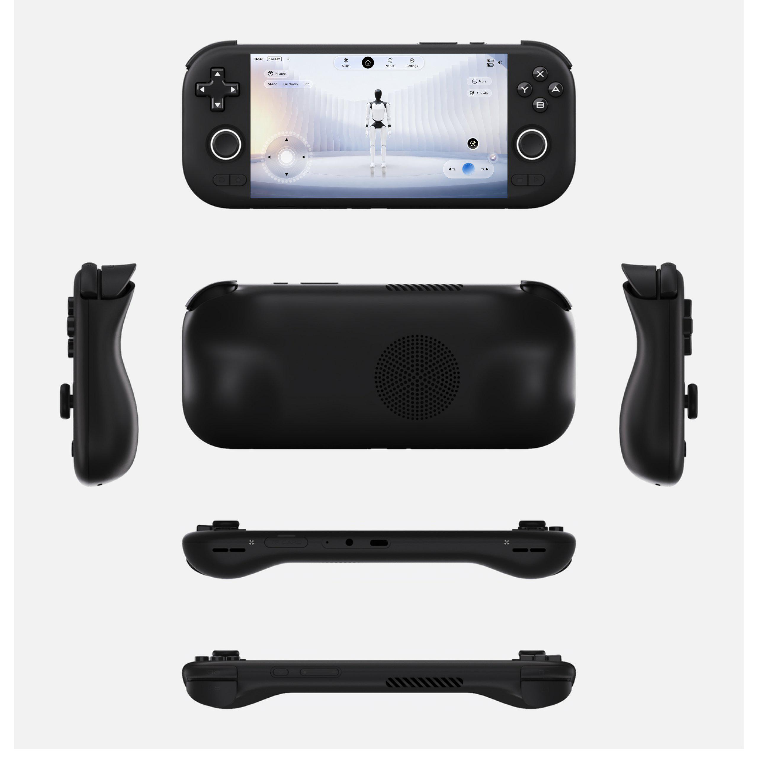
3.1 Remote Control Exterior Design
3.2 Remote Control Button Layout
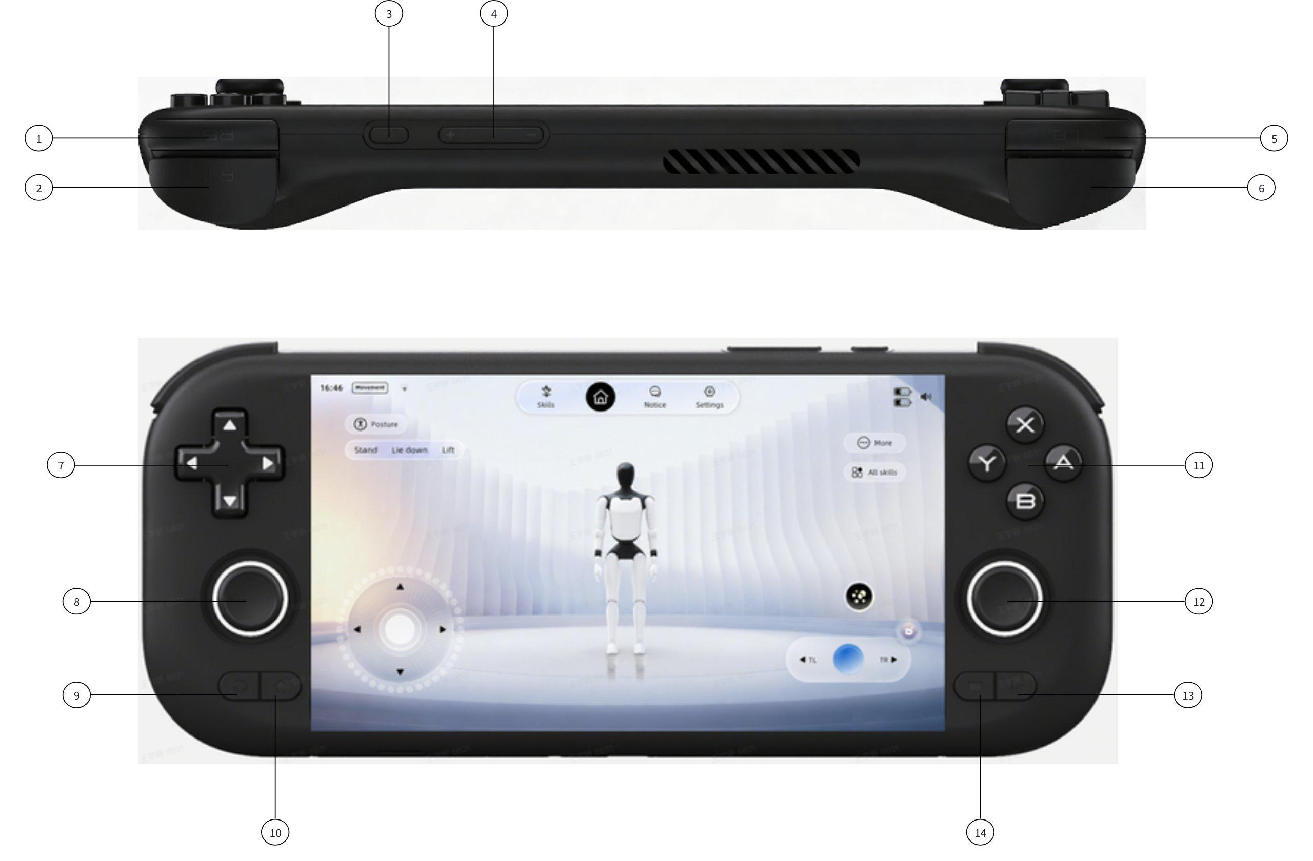
No. | Name | No. | Name |
1 | Left Trigger (L2) | 8 | Left Joystick (L3) |
2 | Left Shoulder Button (L1) | 9 | Back |
3 | Power Button | 10 | Home |
4 | Volume | 11 | A/B/X/Y |
5 | Right Trigger (R2) | 12 | Right Joystick (R3) |
6 | Right Shoulder Button (R1) | 13 | Start |
7 | D-Pad | 14 | Select |
3.3 Remote Control Charging Instructions
Charging Method: The remote control supports charging via a USB-C cable. Do not use a high-power charger, as this may degrade the remote control’s performance.
Battery Life: The remote control typically lasts about 4 hours on a single charge. A full charge takes 3-4 hours. Actual battery life is affected by various factors, and the specific duration depends on actual usage.
Precautions: 1. When using the remote control to operate the Robot, closely monitor the Robot’s battery level. Low battery may prevent switching motion control modes, which could lead to the Robot falling unexpectedly. 9. Use a charger that meets safety standards to charge the remote control. It is recommended to use a 5V/1A or 5V/2A charger to prevent damage from overcharging. |
4. Usage Instructions
4.1 AimMaster
4.1.1 General Guide (How to Connect the Robot)
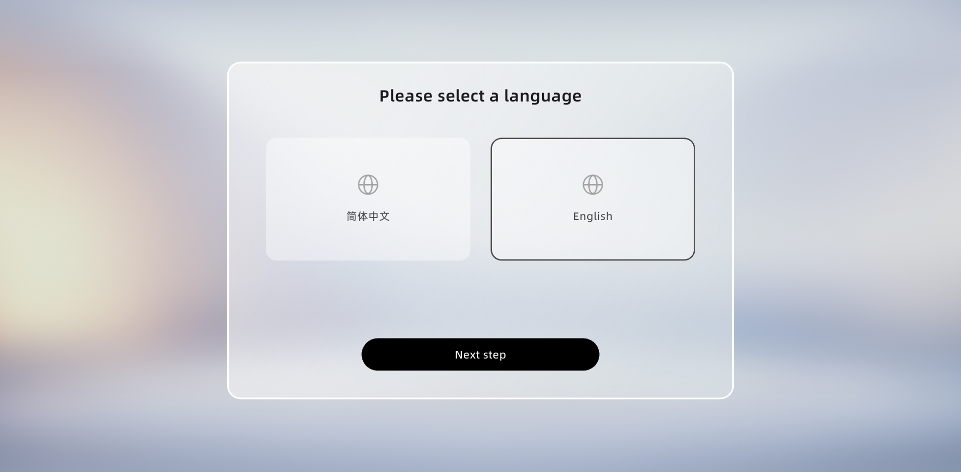
Step 1: Language Selection (Required for First Connection)
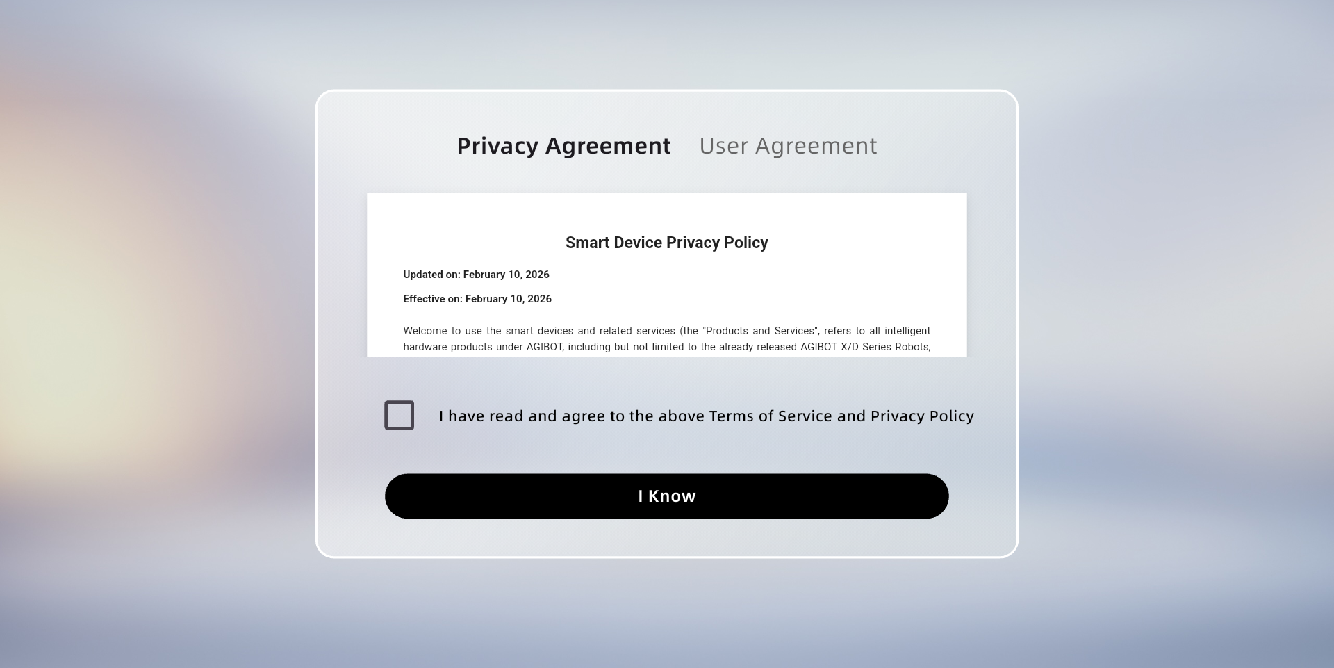
Step 2: Privacy & User Agreement (Required for the first connection)
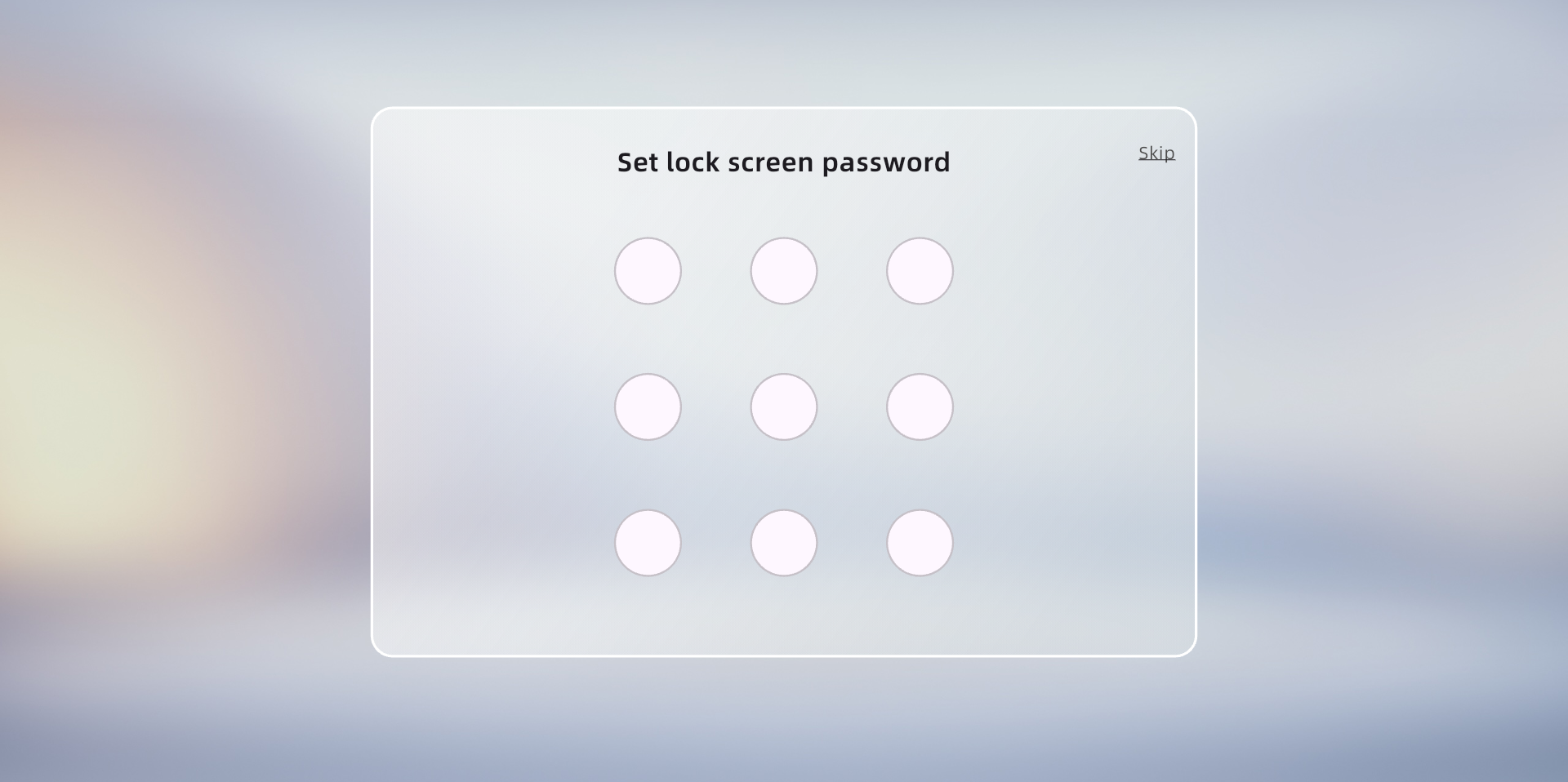
Step 3: Lock screen password setting (required for the first connection)
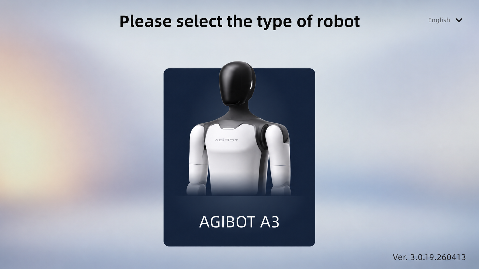
Step 4:Select the robot type
Step 5:Turn on the power
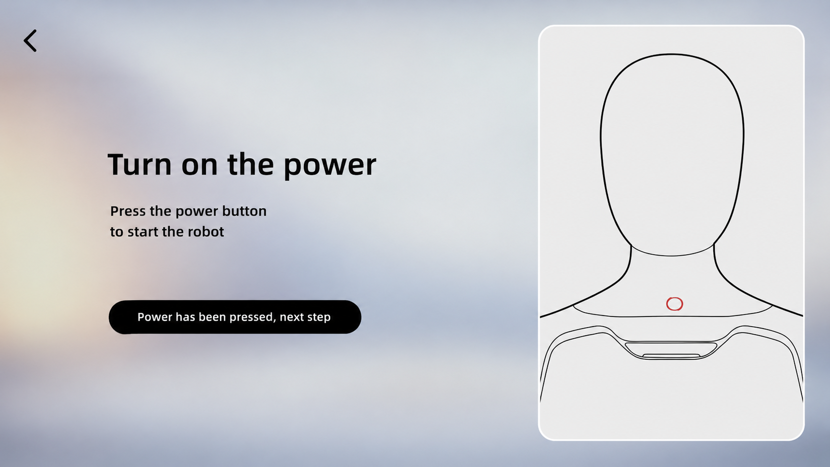
Step 6: Network connection (required for the first connection)
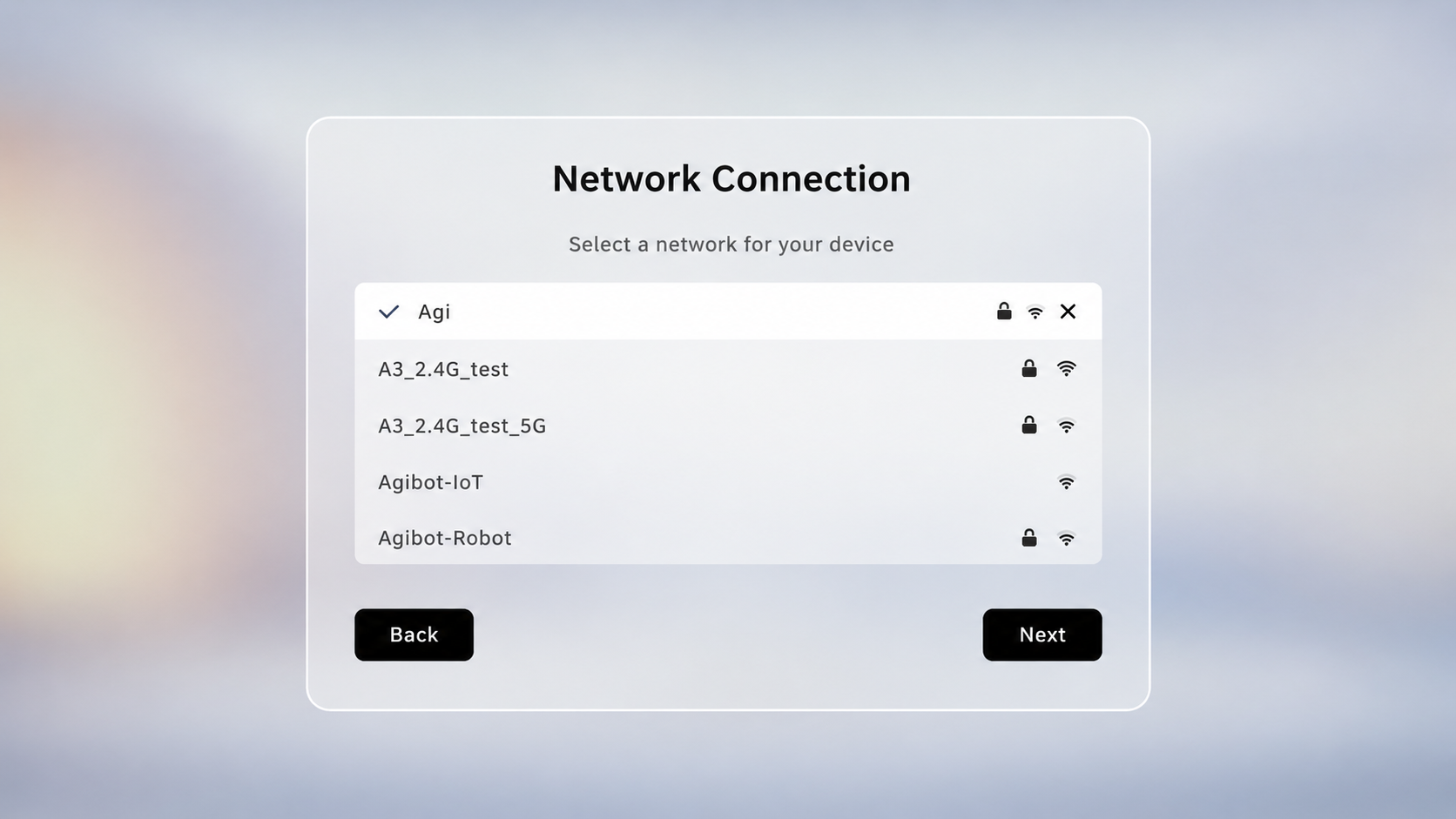
Step 7: Select the robot's language and location (required for the first connection)
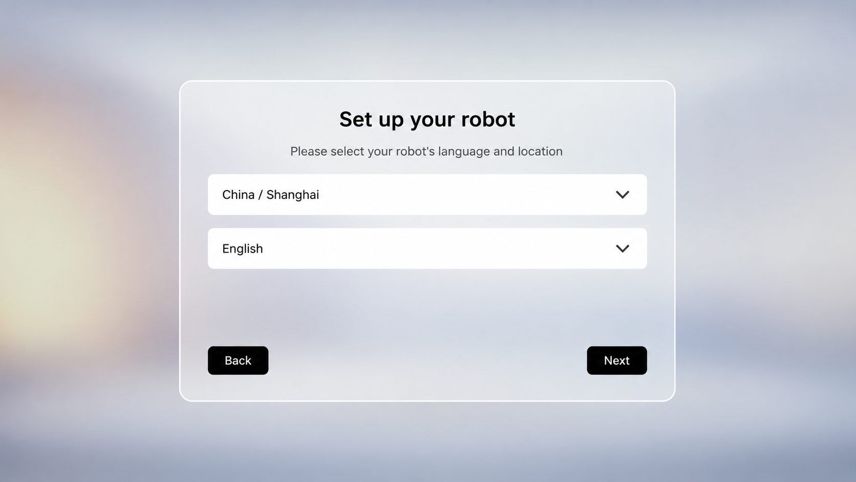
Step 8: Robot authorization password (required for the first connection)
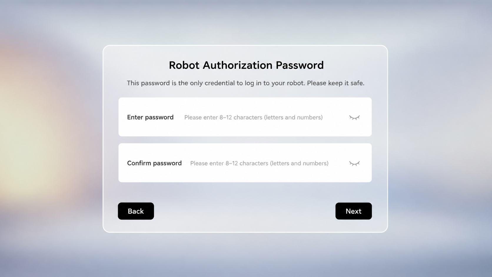
Step 9: Select the robot's posture
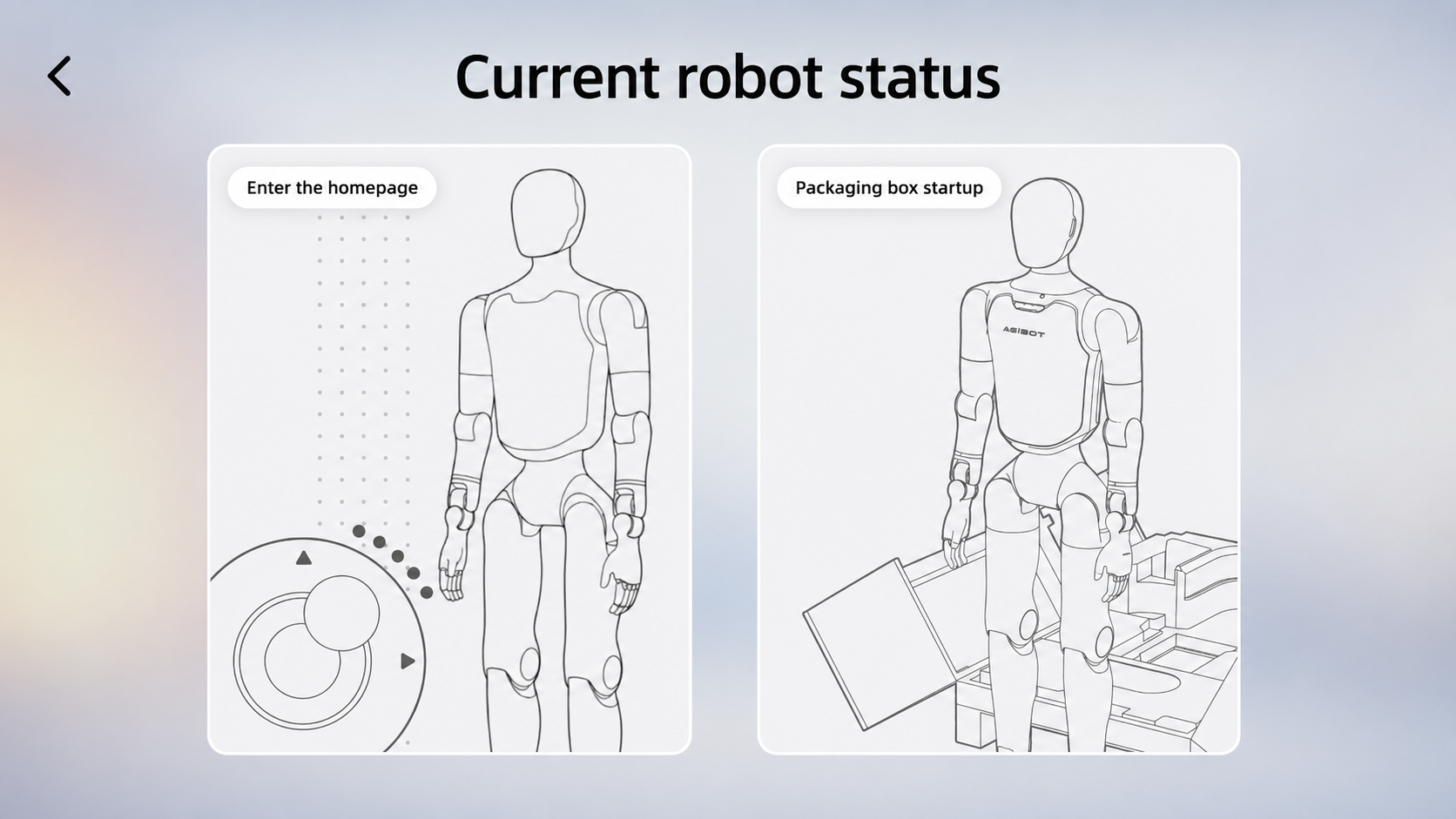
Step 10: Enter the home page
For detailed functionality, refer to the App User Manual https://agirobot.feishu.cn/wiki/HQTdwidb5iPBplkk9iDcpLEPnEe
4.2 Startup Procedure
4.2.1 Packaging Box Startup
Step 1: Activate the battery
Note: This activation step is only required when opening the package for the first time or when the battery pack is in storage and transportation mode.
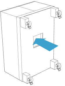
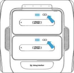
Stand the packaging box upright, open the bottom window, then short press and long press (1s) the power button of each of the two battery packs, until all the indicator lights of the battery packs light up in sequence, indicating successful activation. Then close the bottom window.
Step 1-1: Stand up the packing box and open the bottom window
| Step 1-2: Activate two battery packs
|
Step 2: Open the package
Lay the packing box flat, lock the wheels at the bottom of the packing box after confirming that there are no obstacles in front, then open the top cover of the packing box and remove the middle layer and hip-cover foam, ensuring that there are no items above the robot.
Step 2-1: Place the packing box flat
| Step 2-2: Lock the wheels at the bottom of the packing box
|
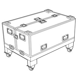
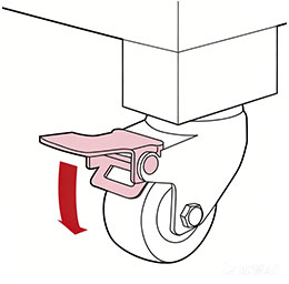
Step 2-3: Unlock and open the top cover of the packaging box
| Step 2-4: Remove the middle layer and hip-cover foam
|
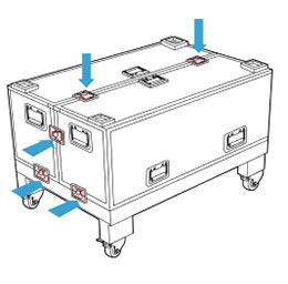
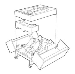
Step 3: Power on and start
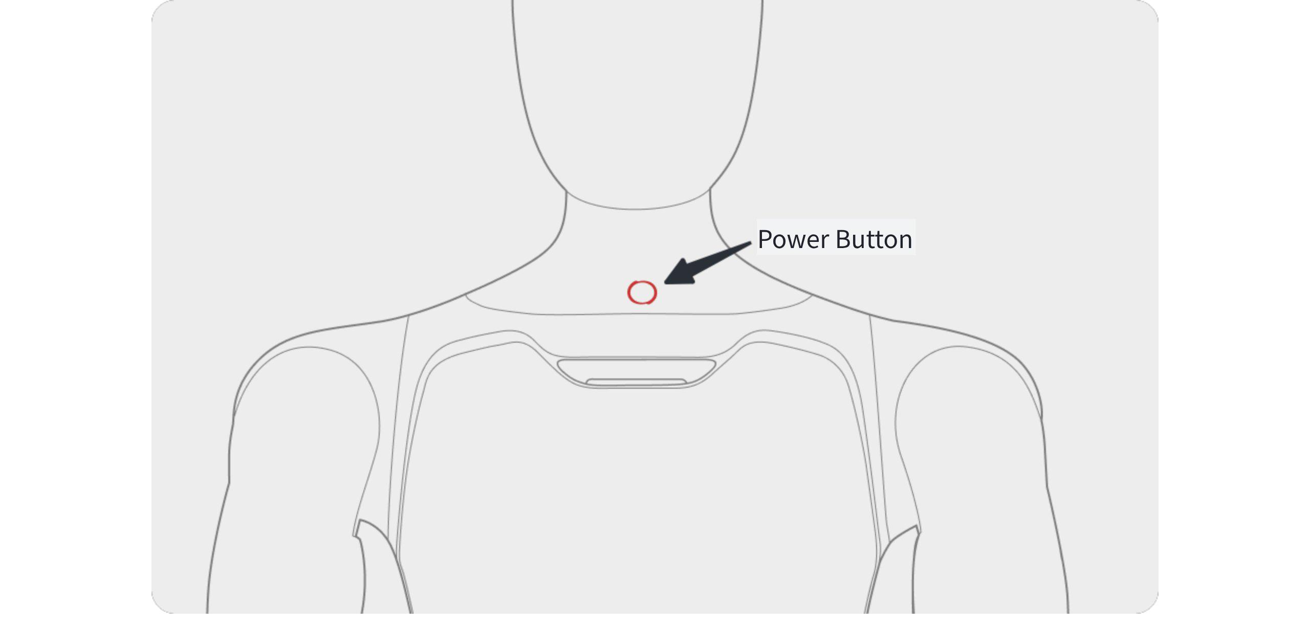
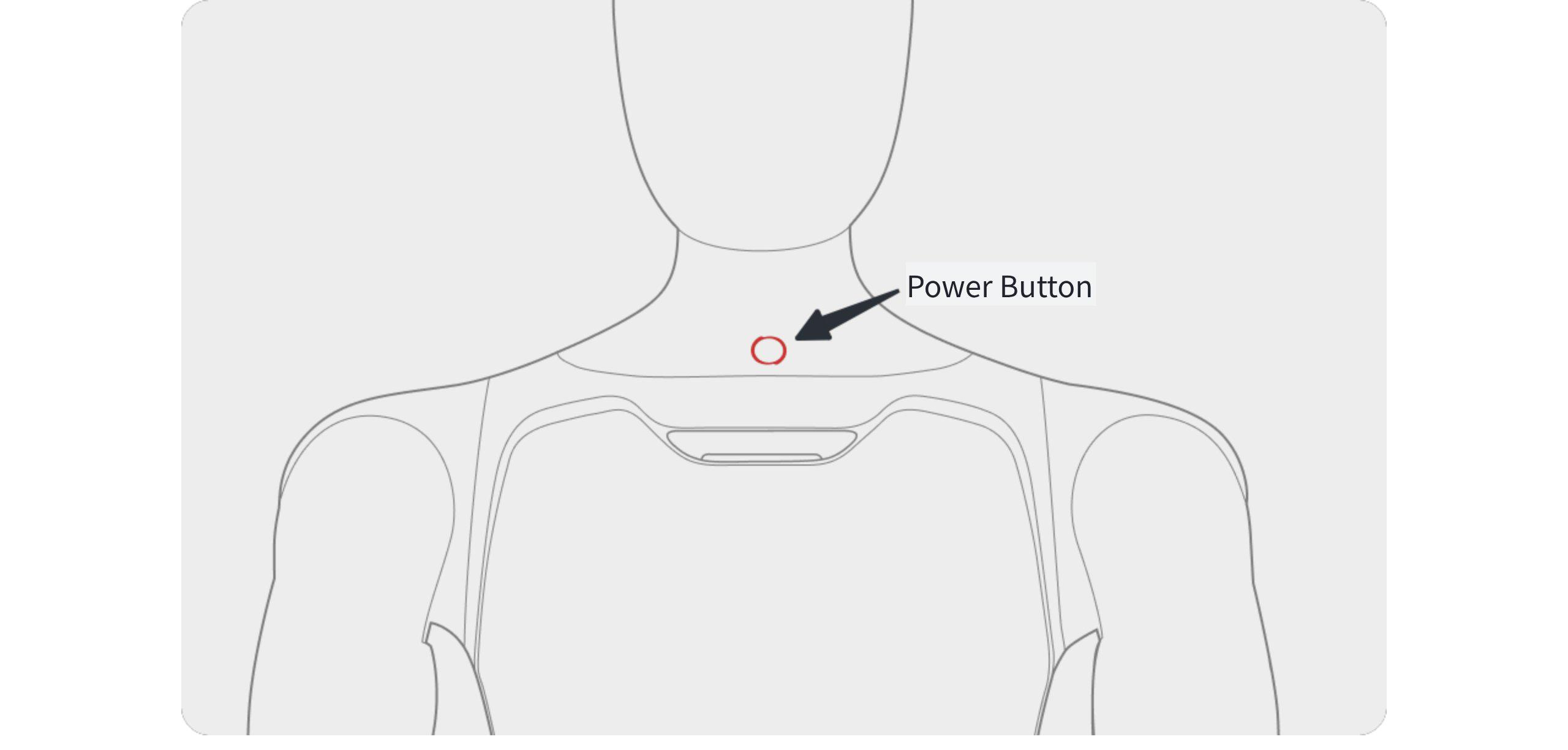
Press and hold the robot’s power button to turn on the robot. After the robot is powered on, the head screen and the indicator light on the chest will light up.
Step 4: Connect to AimMaster
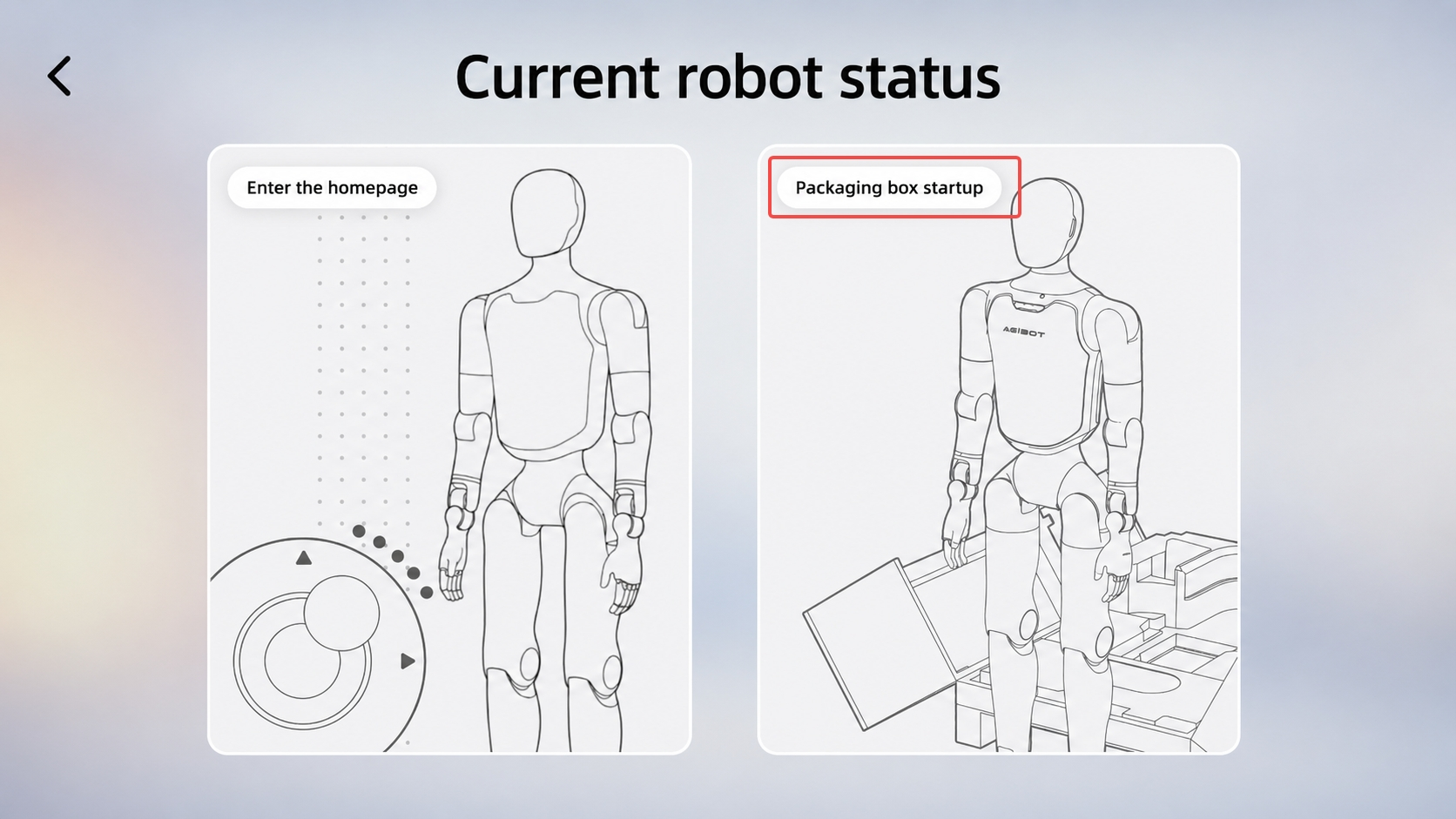
Complete the connection between AimMaster and the robot according to the steps in Section 4.1, and select the [Packaging Box Startup] card on the [Please Select Robot Posture] page.
Step 5: Stand up inside the box
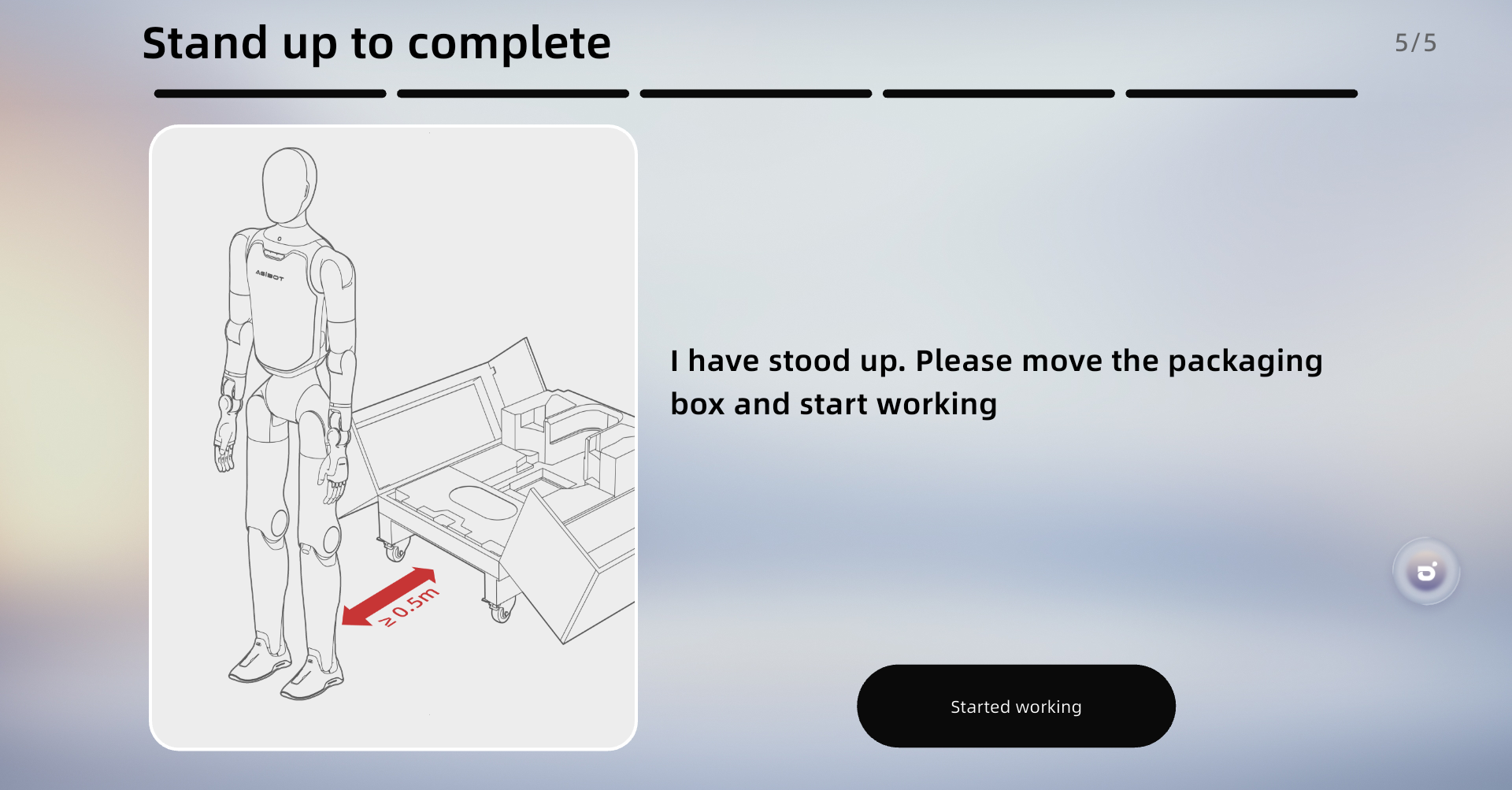
After confirming the environment step by step in AimMaster, control the robot to stand up from the box with one click. The robot will then enter the motion state and maintain a stable standing posture.
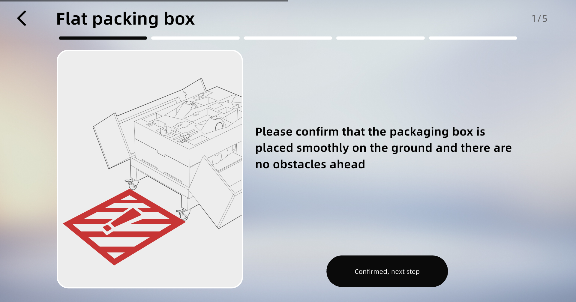
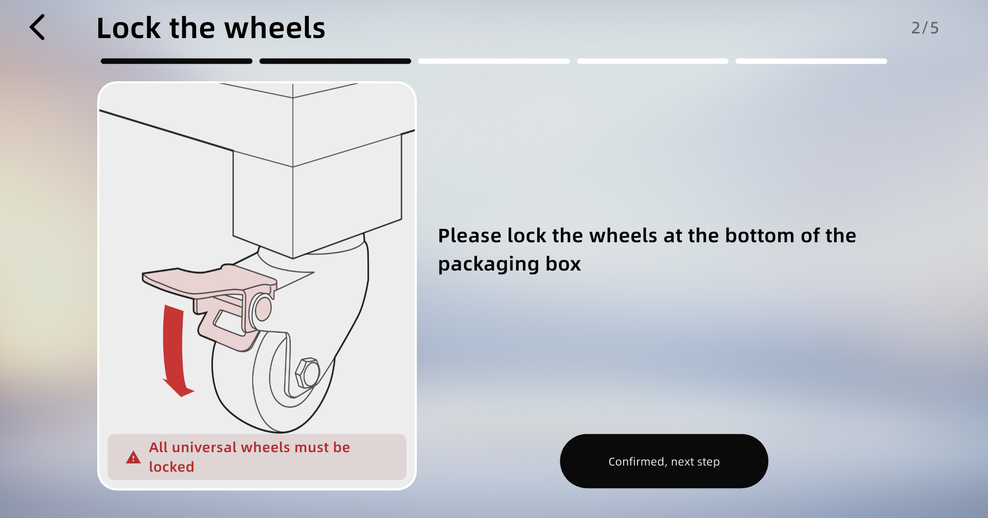
Note: Observe the following: • Ensure no obstacles are present in front of the packaging box. • Lock all casters of the box securely. • Make sure the robot’s hip position is above the red line; adjust it manually above the red line if not. • Do not touch the robot during the stand-up process. • After the robot stands up, move the packaging box at least 0.5 meters away before operation. |
Operation Steps | Operation Interface |
Ensure the packaging box is placed steadily with no obstacles ahead |
|
Confirm the box casters are locked |
|
Confirm the middle layer and hip-cover foam is removed
|
|
Confirm that the robot's position is correct |
|
Confirm initiating the robot stand-up |
|
Robot standing up (automatic) |
|
The robot successfully stands up, moves the packing box away, and ready to use |
|
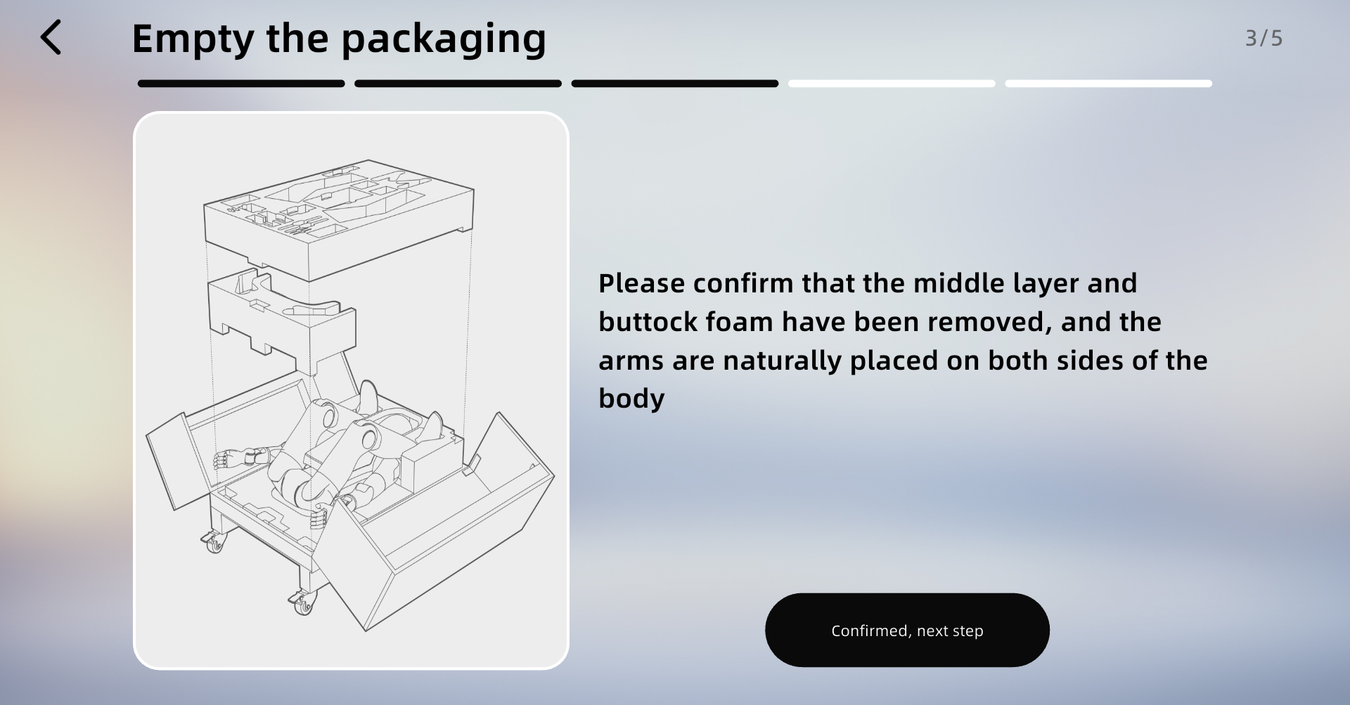
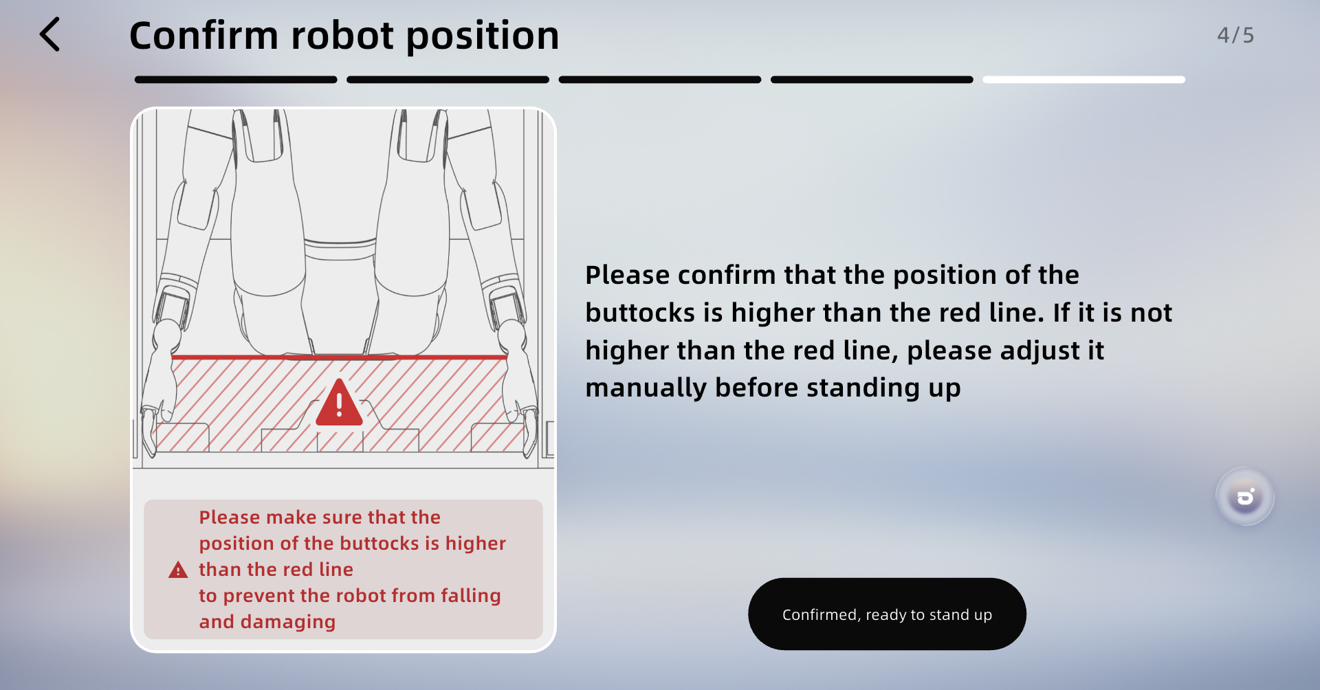
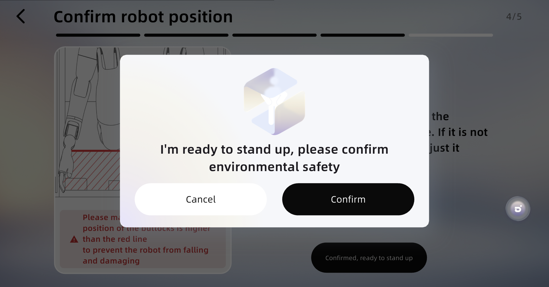
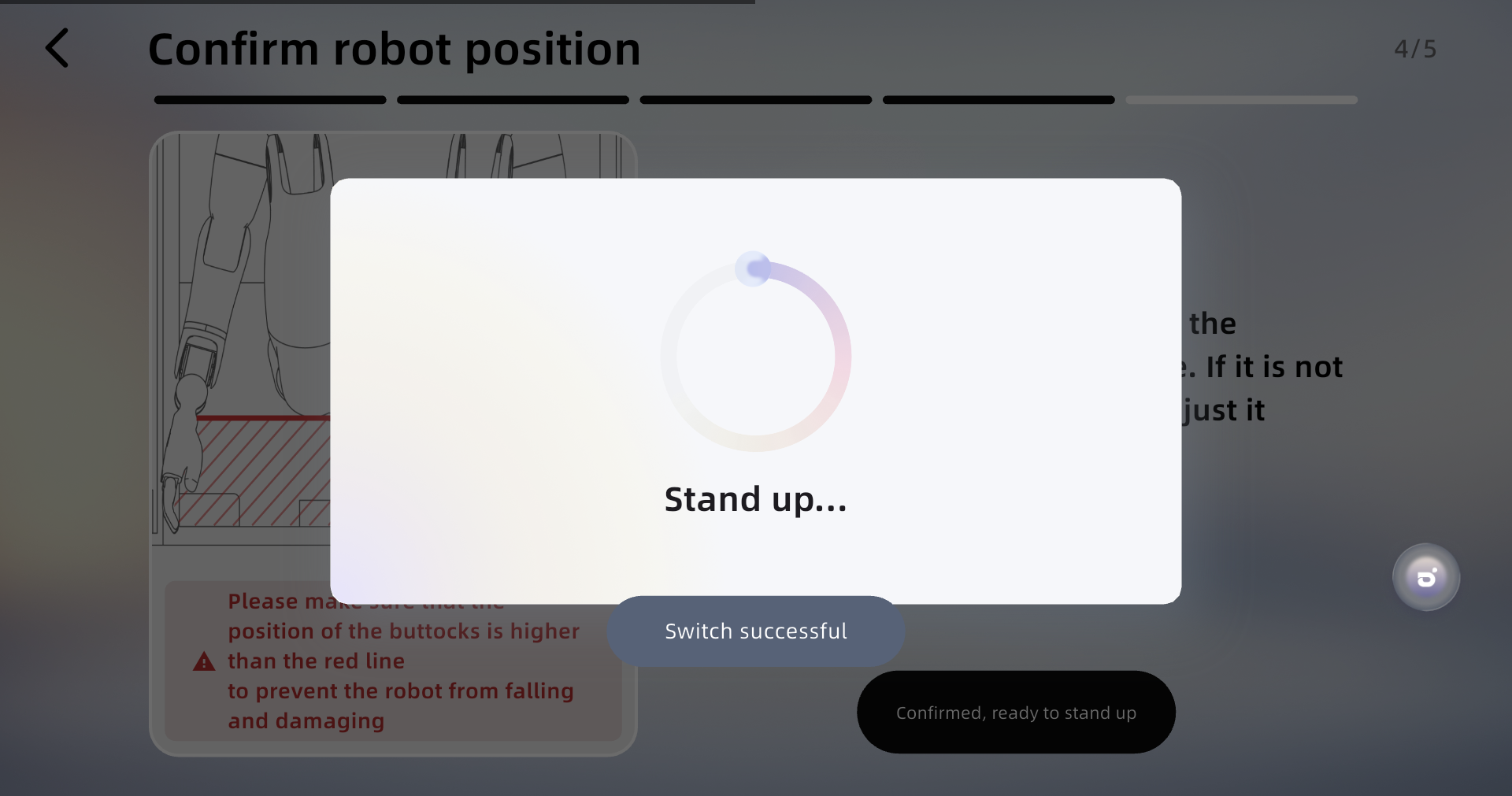
4.2.2 Power On in Supine Position
Step 1: Power on and start
Press and hold the robot’s power button to turn on the robot. After the robot is powered on, the head screen and the indicator light on the chest will light up.
Note: If the battery pack is in storage and transportation mode, it is necessary to activate the battery pack before powering on. The operation method is to short press and then long press (1s) the power button on the battery pack, until all the battery pack indicator lights light up sequentially. |
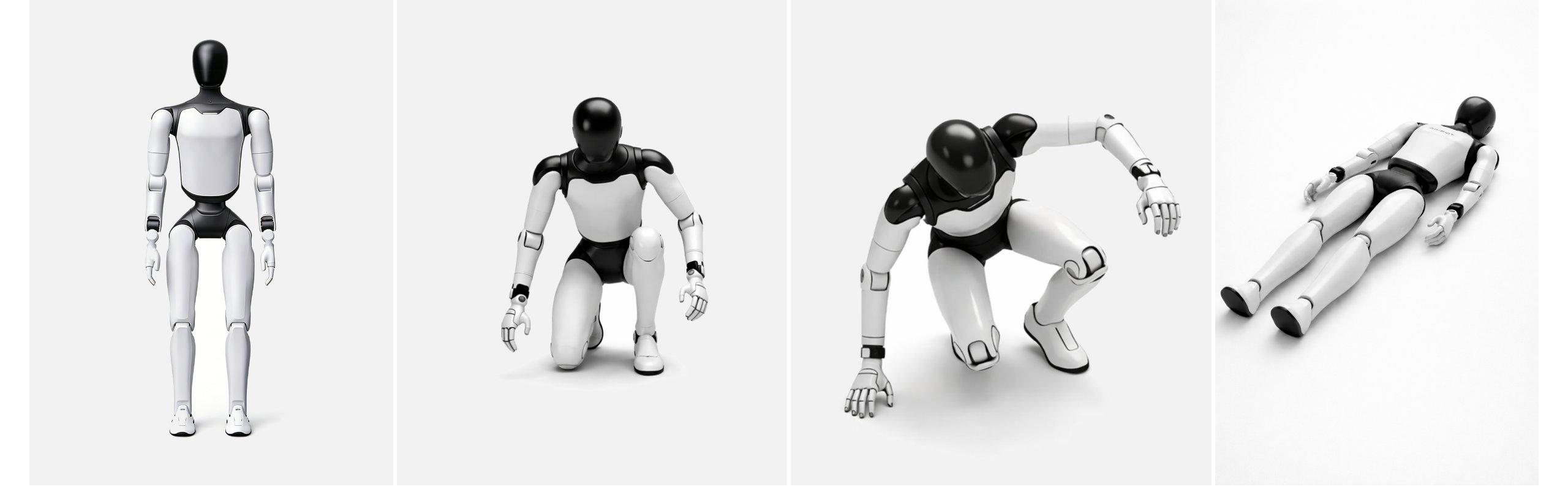
Step 2: Lay the robot flat
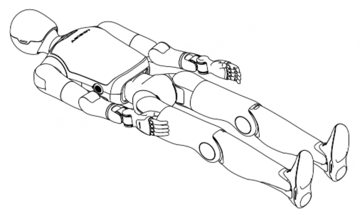
Lay down the robot on a flat surface as shown in the following illustration, ensuring that the entire body of the robot faces upward, its limbs are extended, and its arms are naturally placed on both sides of the body.
Step 3: Connect to AimMaster
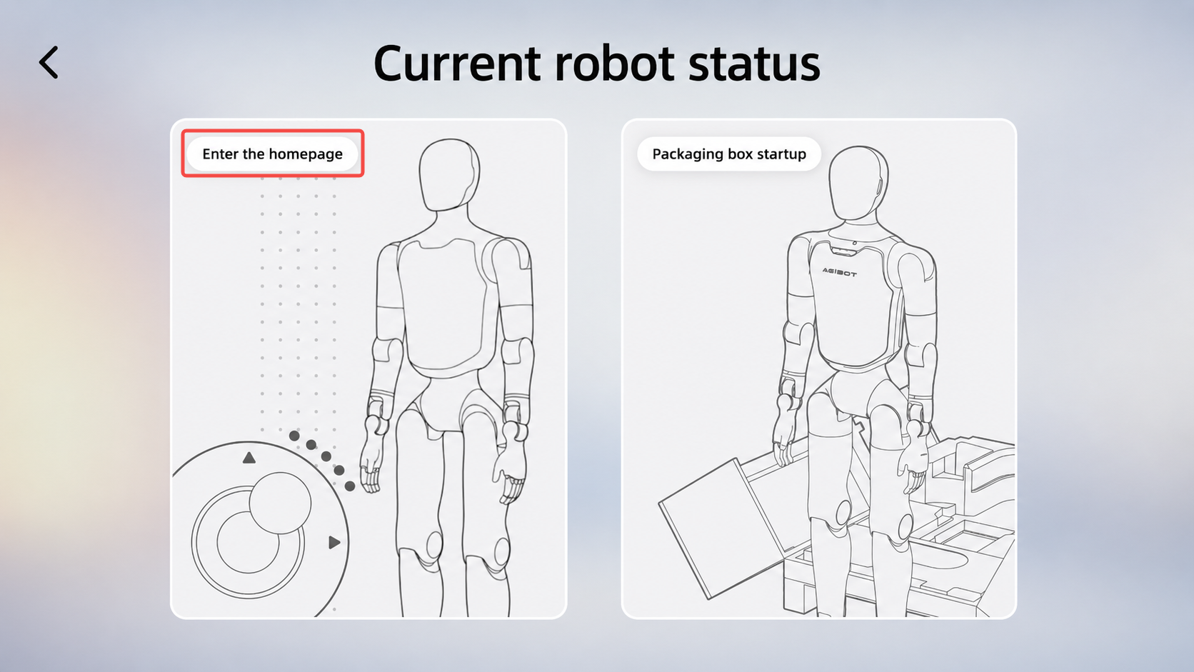
Complete the connection between AimMaster and the robot according to the steps in Section 4.1, and select the homepage entering option on the robot status page.
Step 4: Confirm environmental safety
Before triggering the lying-down-to-standing-up action, it is necessary to ensure that there are no foreign objects within a 1-meter radius around the robot to reserve sufficient safety space for the action execution.
Step 5: Stand up from lying flat
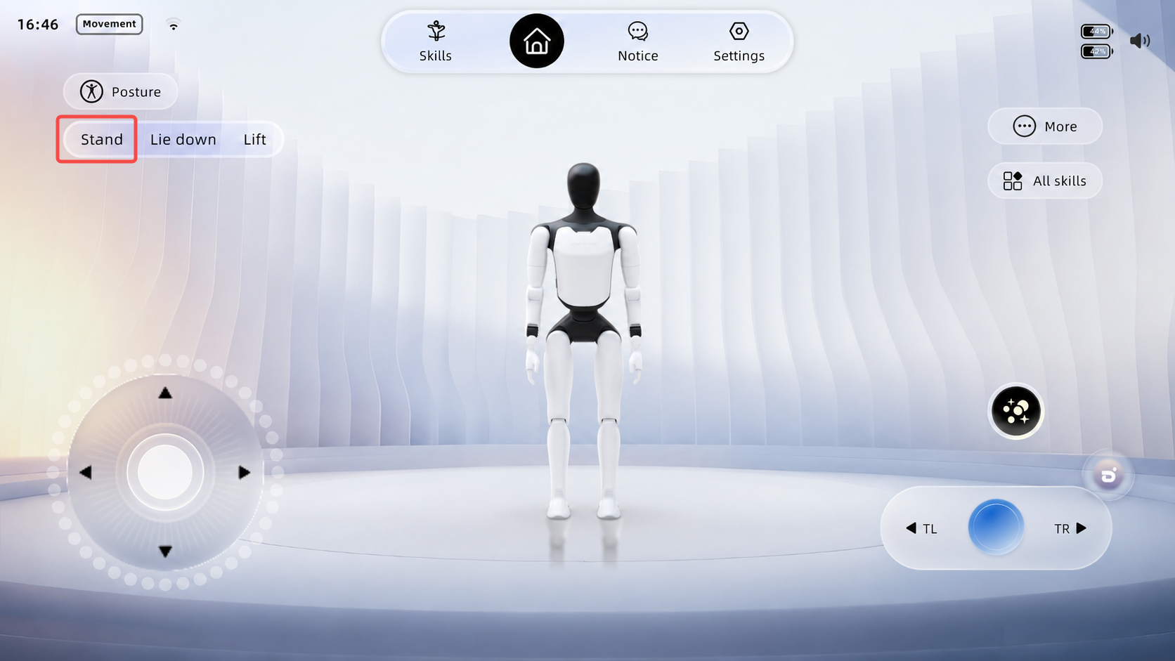
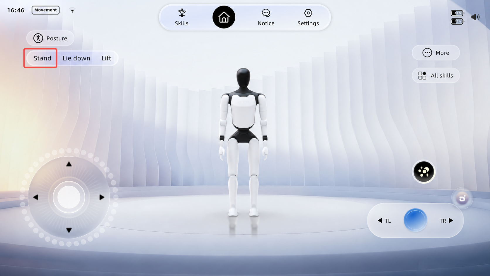
Under the Posture switch on the home page of AimMaster, choose "Stand" to enable the robot to stand up from a lying position. At this time, the robot enters a motion state and stands stably.
4.2.3 Power On in Prone Position
Step 1: Power on and start
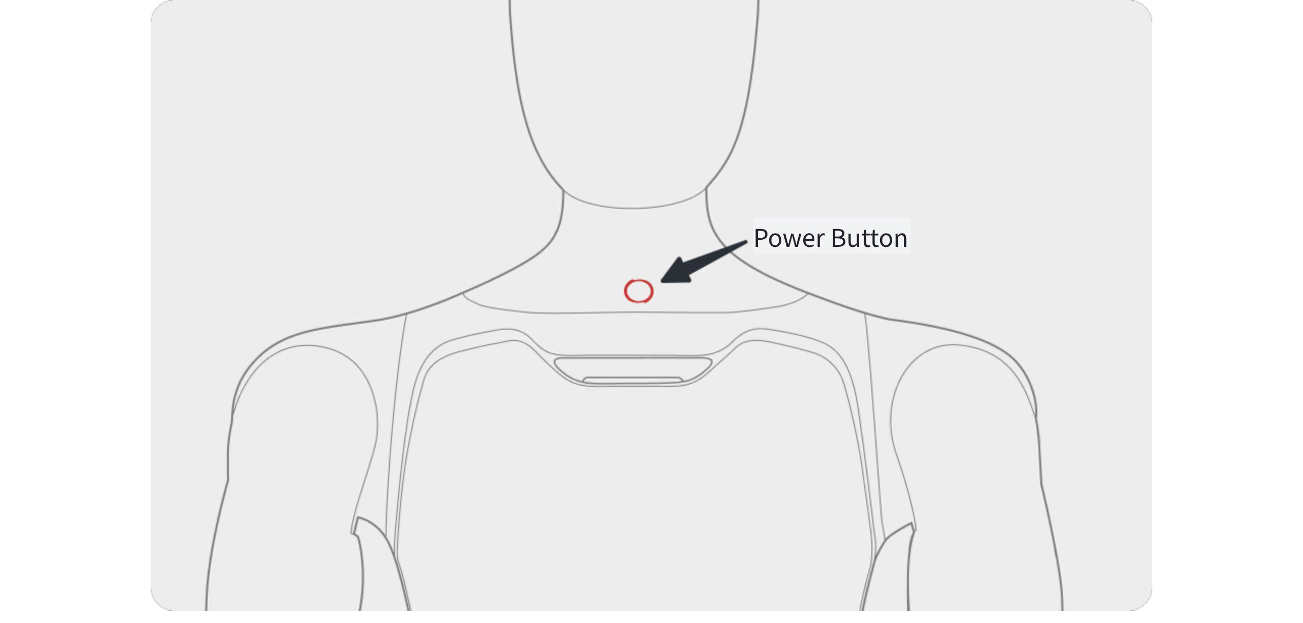
Press and hold the robot’s power button to turn on the robot. After the robot is powered on, the head screen and the indicator light on the chest will light up.
Note: If the battery pack is in storage and transportation mode, it is necessary to activate the battery pack before powering on. The operation method is to short press and then long press (1s) the power button on the battery pack, until all the battery pack indicator lights light up sequentially. |
Step 2: Lay the robot face-down
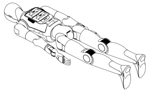
Lay the robot face-down on a flat surface as shown in the illustration, ensuring that the entire body of the robot faces downward, its limbs are extended, and its arms are naturally positioned on both sides of the body.
Step 3: Connect to AimMaster
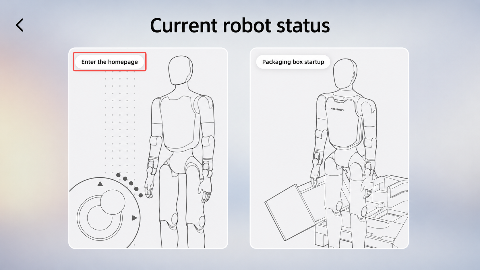
Complete the connection between AimMaster and the robot according to the steps in Section 4.1, and select the homepage entering option on the robot status page.
Step 4: Confirm environmental safety
Before triggering the prone-to-standing action, it is necessary to ensure that there are no foreign objects within a 1-meter radius around the robot to reserve sufficient safety space for the action execution.
Step 5: Stand up from a prone position
Under the Posture switch on the home page of AimMaster, choose "Stand" to enable the robot to stand up from a lying position. At this time, the robot enters a motion state and stands stably.
4.3 Shutdown Procedure
4.3.1 Shutdown and Packing
Note: Observe the following: • When moving the packing box to align with the robot, be sure not to hit the robot. • Before the robot enters the packaging, confirm that all casters have been locked. • Do not touch the robot during the return-to-box process. • After shutdown, wait until the chest indicator light goes off (about 20 s). • In case of a fault, press and hold the power button for 30 s to force shutdown. |
Step 1: The robot is in motion and standing stably
Step 2: Initiate the self-service return process
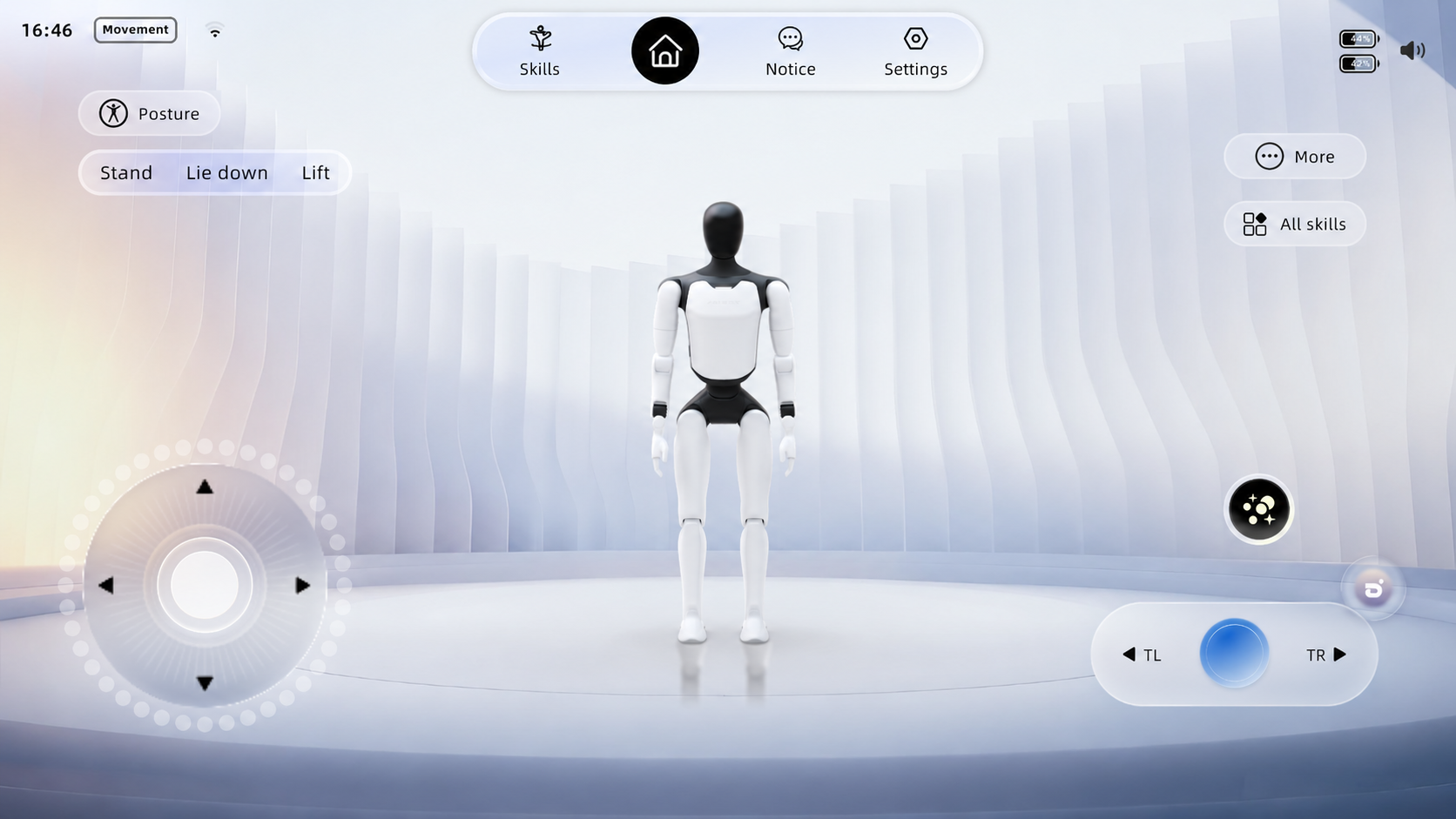
On the-page of AimMaster, choose, and start the return-to-box process after ensuring the surface is level.
Step 3: Move and position the packaging box
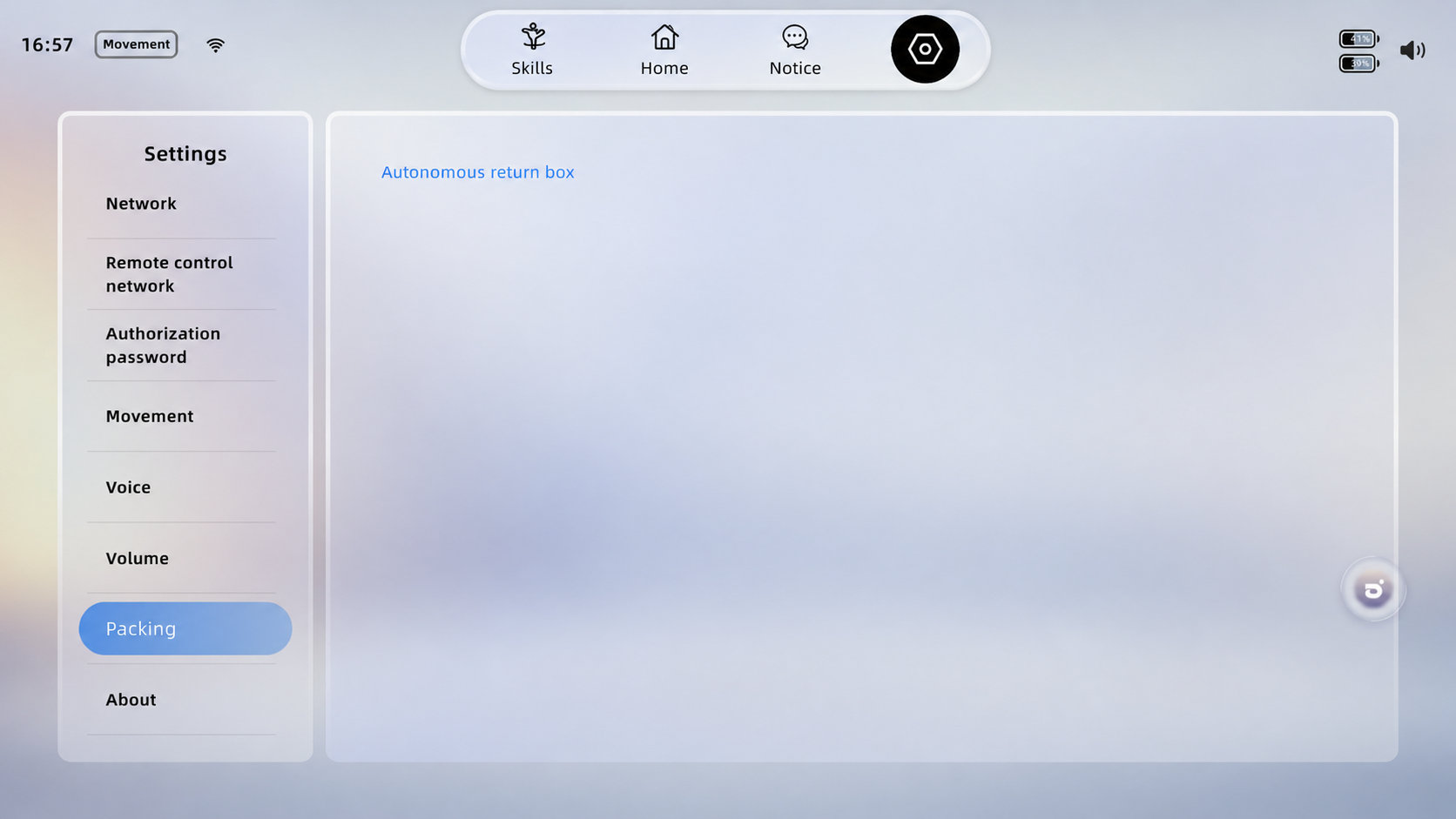
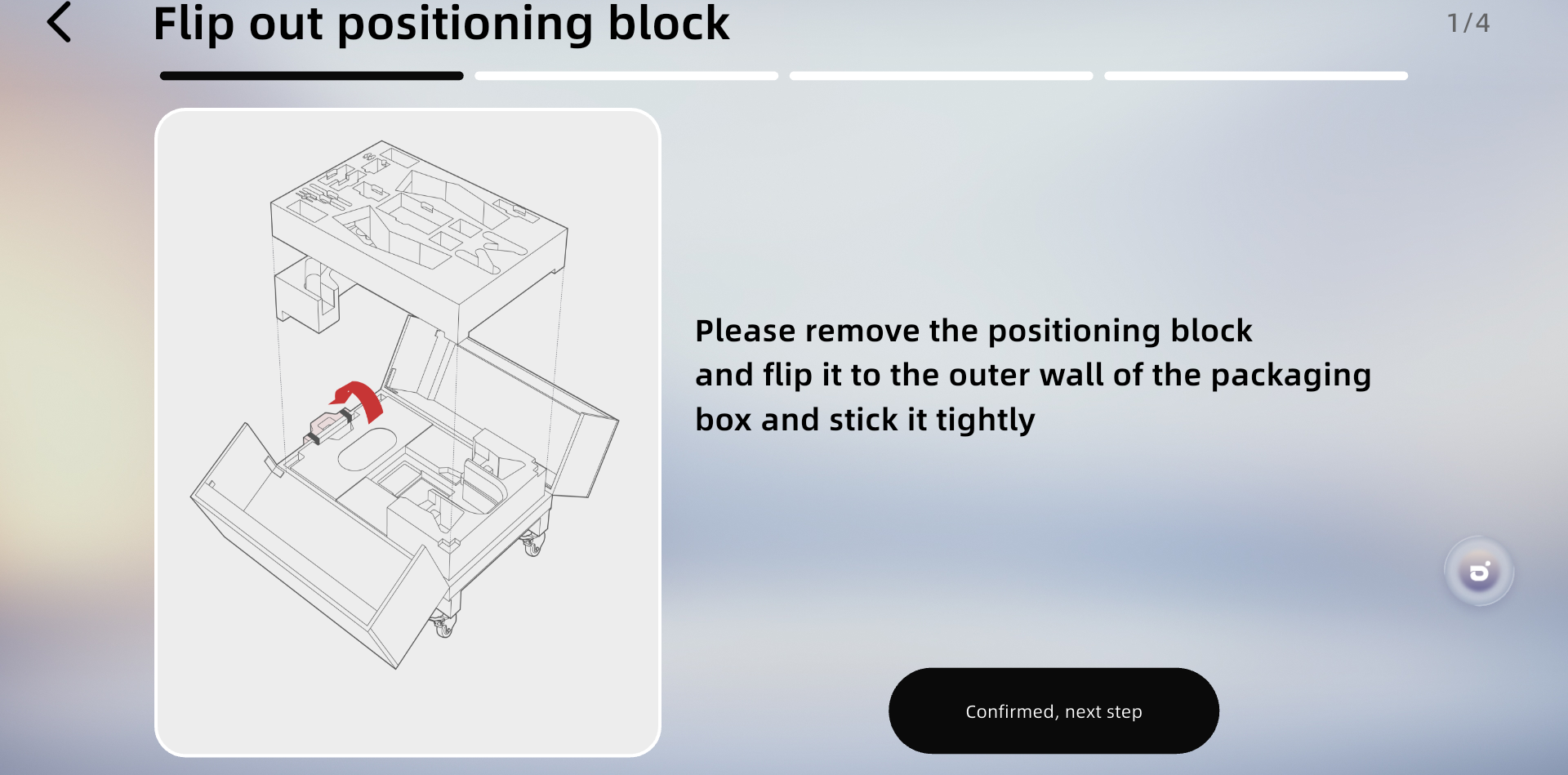
Pull out the positioning block from inside the packing box, turn it over to the outer wall of the packing box and press it firmly against the wall; move the packing box to the back of the robot so that the positioning block gently touches both legs and centers itself for positioning.
Step 3-1: Flip out the positioning block
| Step3-2: Align the robot
|
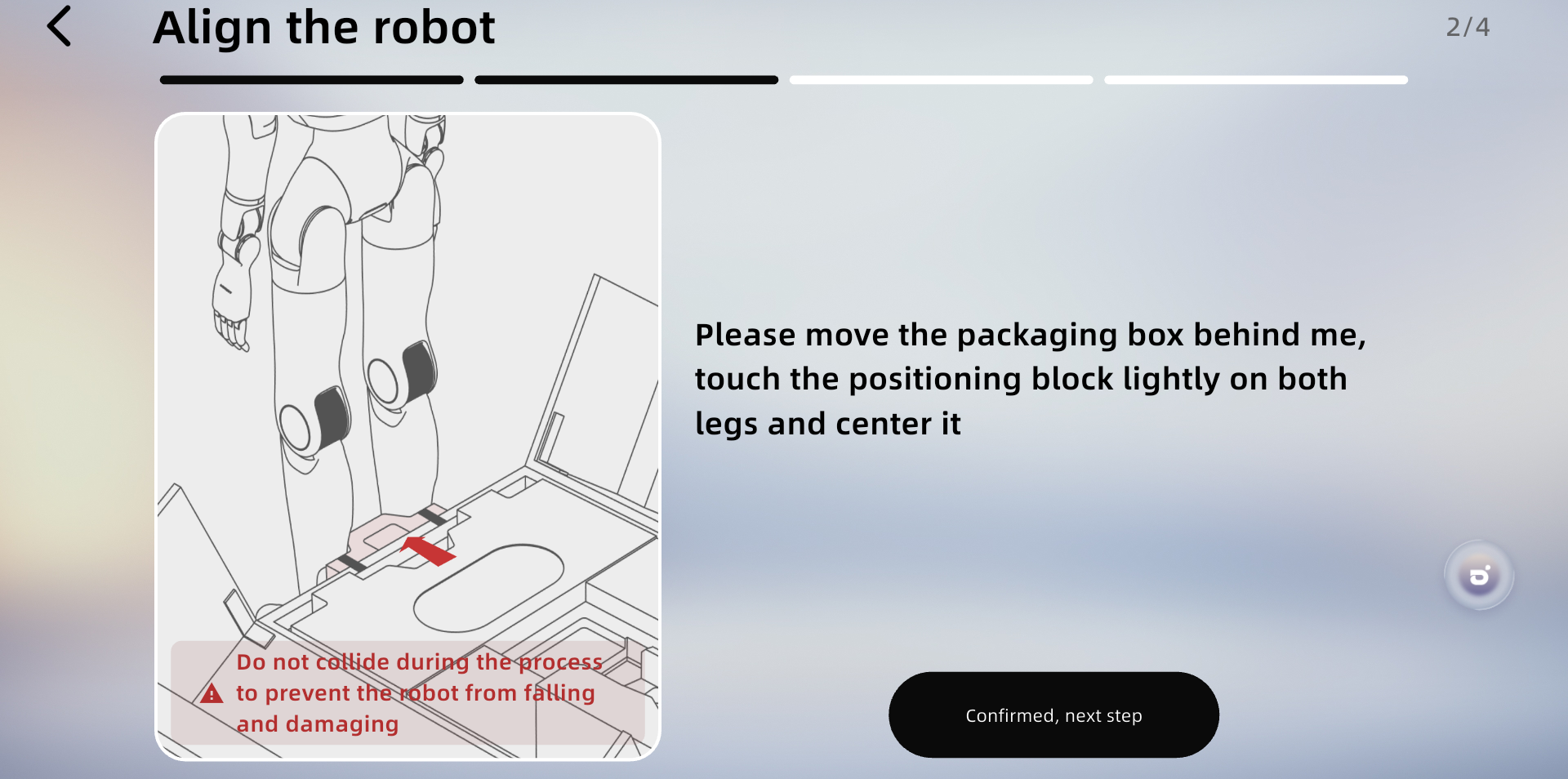
Step 4: Lock the packing box
Lock all the casters of the packing box, and confirm that the inside of the packing box has been cleaned up.
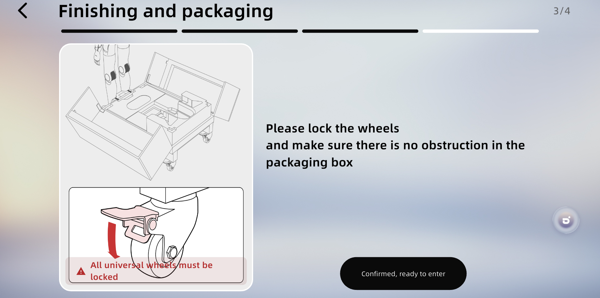
Step 5: Robot returns to the box
After confirming environmental safety, confirm to start entering the packaging box.
Step 6: Shut down and pack
After the robot is placed inside the packaging box, briefly press the power button on the chest, and follow the voice prompts to turn it off; then insert the positioning block, hip-cover foam, and middle layer foam back into their original positions to secure and protect the robot; finally, close the packaging box and lock it.
4.3.2 Shutdown with Supine Position
Caution: Ensure a 1-meter radius safety space around the robot to avoid collisions. |
Step 1: The robot is in motion mode, use the remote control to connect to the robot
|
|
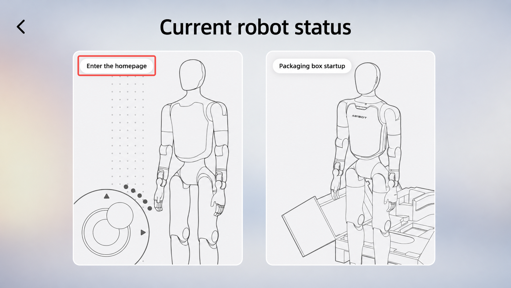
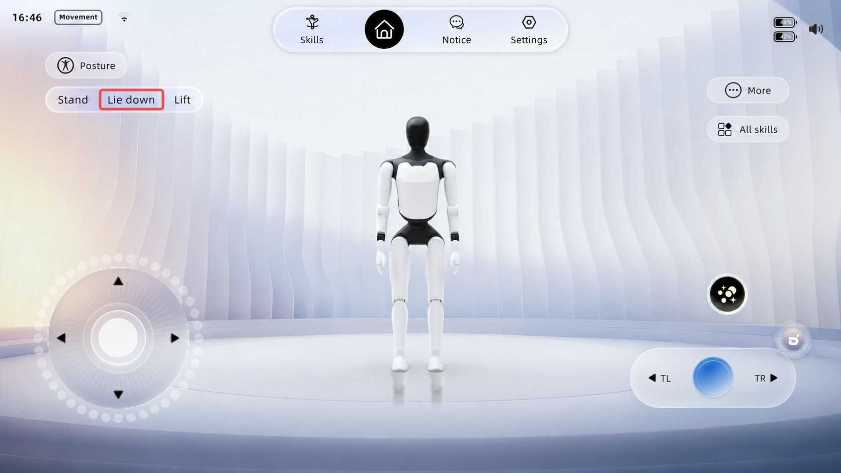
Step 2: Remote control the robot to lie flat
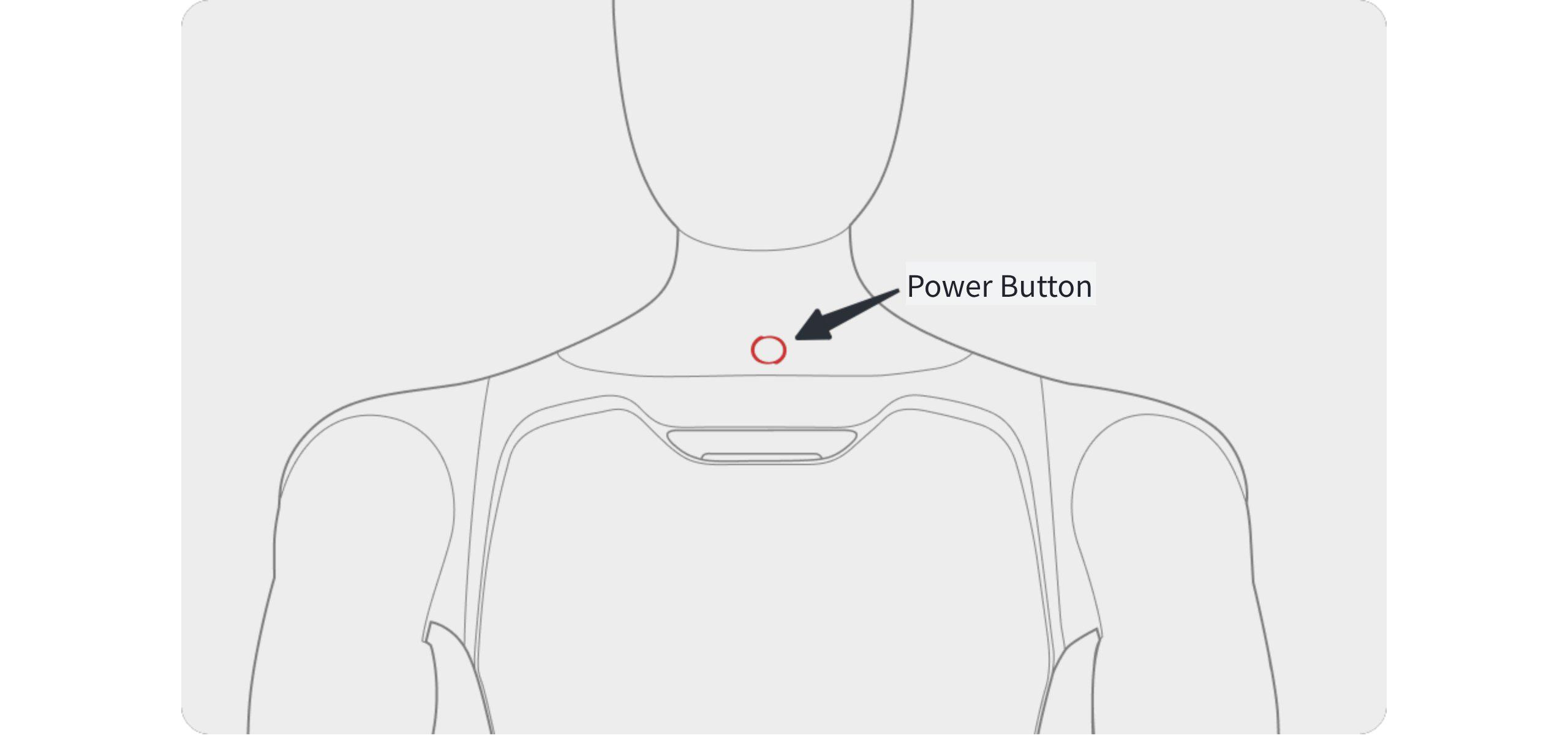
Step 3: Short press the power button on the chest, and follow the voice prompts to turn off the device
4.4 Entering and Exiting Battery Pack Storage Mode
Note: Before transportation or long-term storage, it is recommended to enable the battery pack storage mode.If the robot is powered off without entering Storage Mode, the system will still consume approximately 7W of standby power, and a fully charged battery pack may be completely depleted in about 7 days. |
4.4.1 Enter Storage Mode
Step 1: Press the battery pack power button briefly 5 times continuously. After the red indicator starts flashing, press and hold the power button.
Step 2: Continue holding the button until the green indicator starts flashing, then release the button. The battery pack has now entered Storage Mode.
Storage Mode Activation Check:
Briefly press the battery pack power button once. If the battery indicator lights up only after a few seconds, Storage Mode has been successfully activated.
4.4.2 Exit Storage Mode
Step 1: Briefly press the battery pack power button once to make all green indicators light up, and perform the Storage Mode check.
Step 2: Immediately press and hold the power button again. When the indicator light sequence completes, the battery pack has been successfully activated and has exited Storage Mode.
4.5 Charging and Battery Changing
4.5.1 Charging Mode
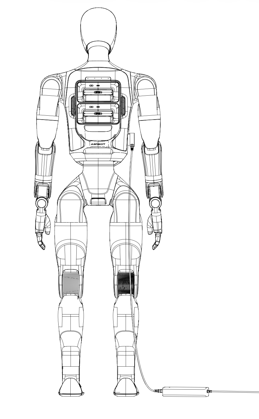
1. Charging the robot with battery installed
When both batteries are in place, the magnetic charging head of the charger can be connected to the charging port of the robot. After the power is turned on, the magnetic charging head of the charger lights up green, indicating successful charging. The schematic diagram is as follows:
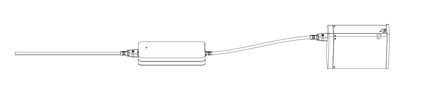
2. Charging the battery solely
Remove the battery and separate the magnetic adapter section of the charger to directly charge the battery. The schematic diagram is as follows:
4.5.2 Battery Changing Mode
Note: If the battery pack is in storage and transportation mode, it is necessary to activate the battery pack before powering on. The operation method is to short press and then long press (1s) the battery pack power button until all the battery pack indicator lights light up sequentially. |
Step 1: Remove an individual battery
Step 2: Insert the "new" battery
Step 3: Repeat the above actions and replace the second battery
* An individual battery can be removed in both the shutdown state and the powered-on standing state (when only a single battery is left in place, the robot is restricted from moving).
Note: If the battery pack is in storage and transportation mode, it is necessary to activate the battery pack before powering on. The operation method is to short press and then long press (1s) the battery pack power button until all the battery pack indicator lights light up sequentially. |
4.5.3 Autonomous Charging
4.5.3.1 Functional Overview
• Autonomous charging is a prerequisite for the robot to achieve 7 x 24-hour autonomous operation. • When the robot needs recharging, it autonomously navigates to the charging point and completes actions such as identifying and plugging in the charging gun to start charging; after charging is complete, it autonomously performs the wrap-up actions — unplugging, holstering the gun, and retracting the arm — and ends charging on its own. |
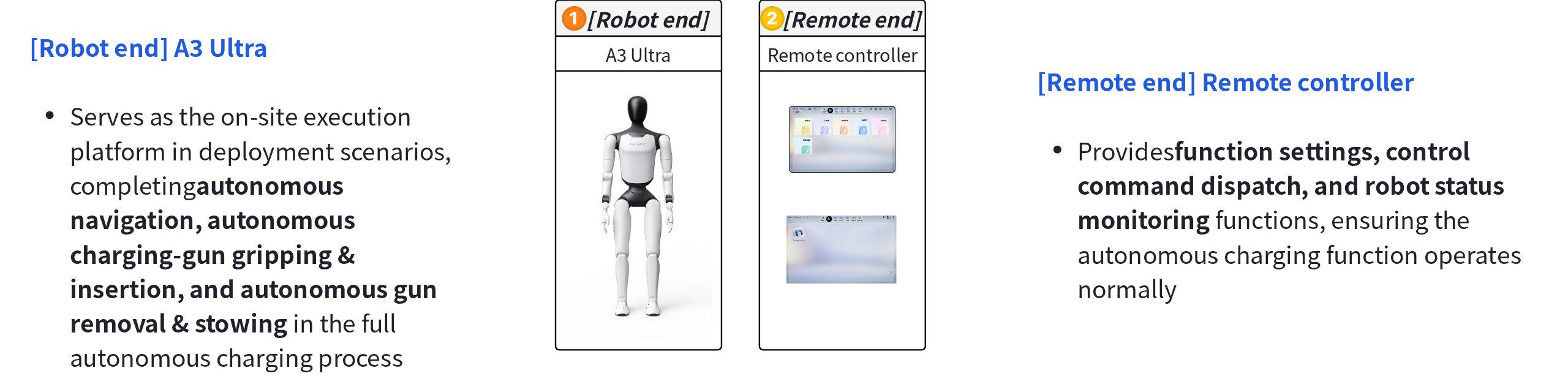

4.5.3.2 Preparation
Prerequisites: Complete mapping first, and make sure the robot is in motion mode and has been localized on the current map. This section covers the autonomous charging function only; for mapping, navigation, and relocalization, refer to the corresponding user manuals. |
4.5.3.2.1 Deploying the Charging Point
1. Fix the charging gun base to the edge of a light-colored table with the fixing clip (deployment on dark-colored tables is not supported in this release); table height: 75–95 cm. Connect the other end to a power supply.
2. Attach the charging point marker board in the orientation shown: align its bottom edge with the table edge and press its right edge tightly against the charging gun base; peel off the protective film on the back and stick it to the desktop.
3. Remote-control the robot to the table where the charging gun is fixed.
Secure the charging connector to the edge of the table |
Attach the charging-point marker |
Use the remote controller to move the robot next to the table. |
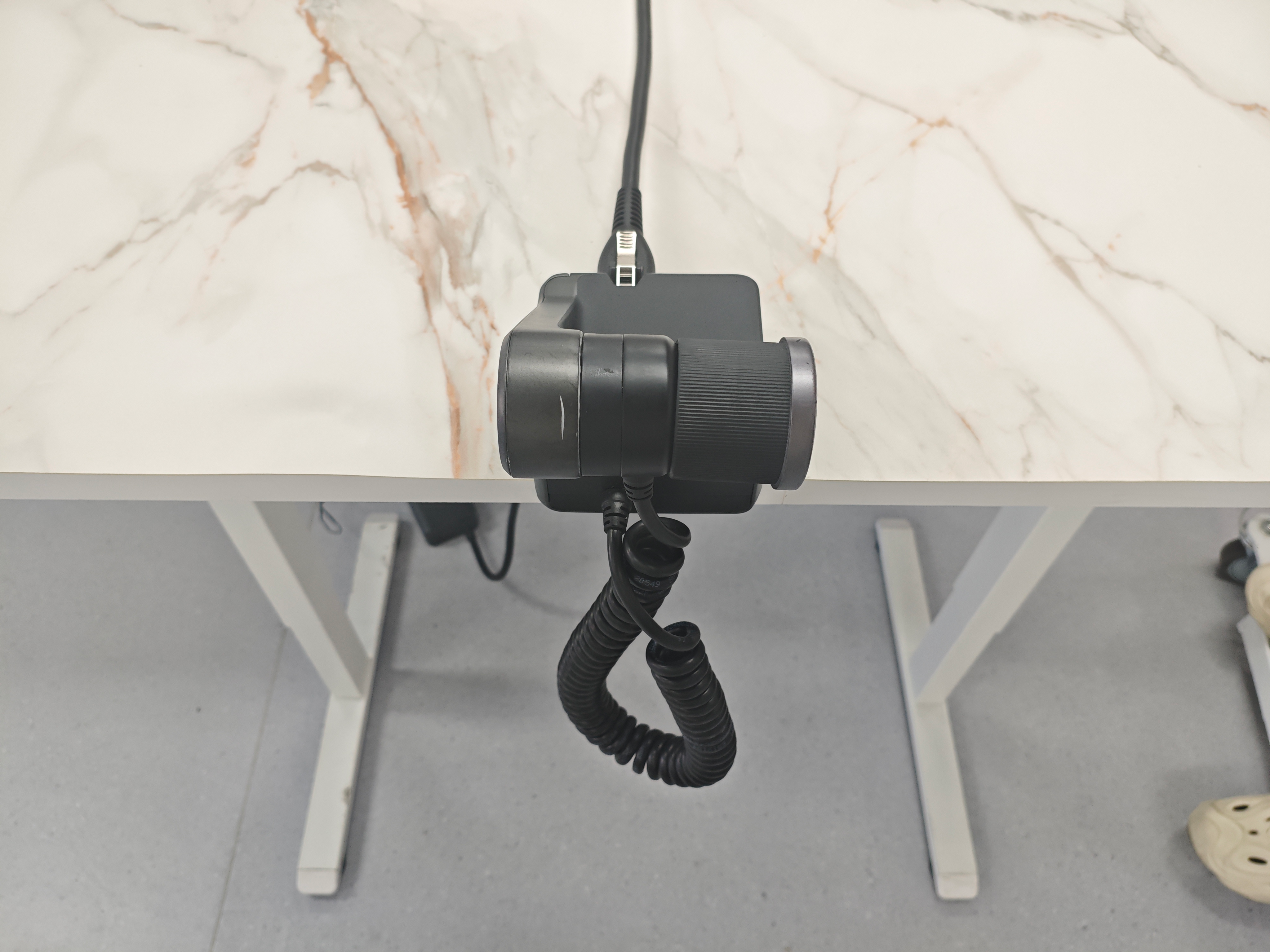
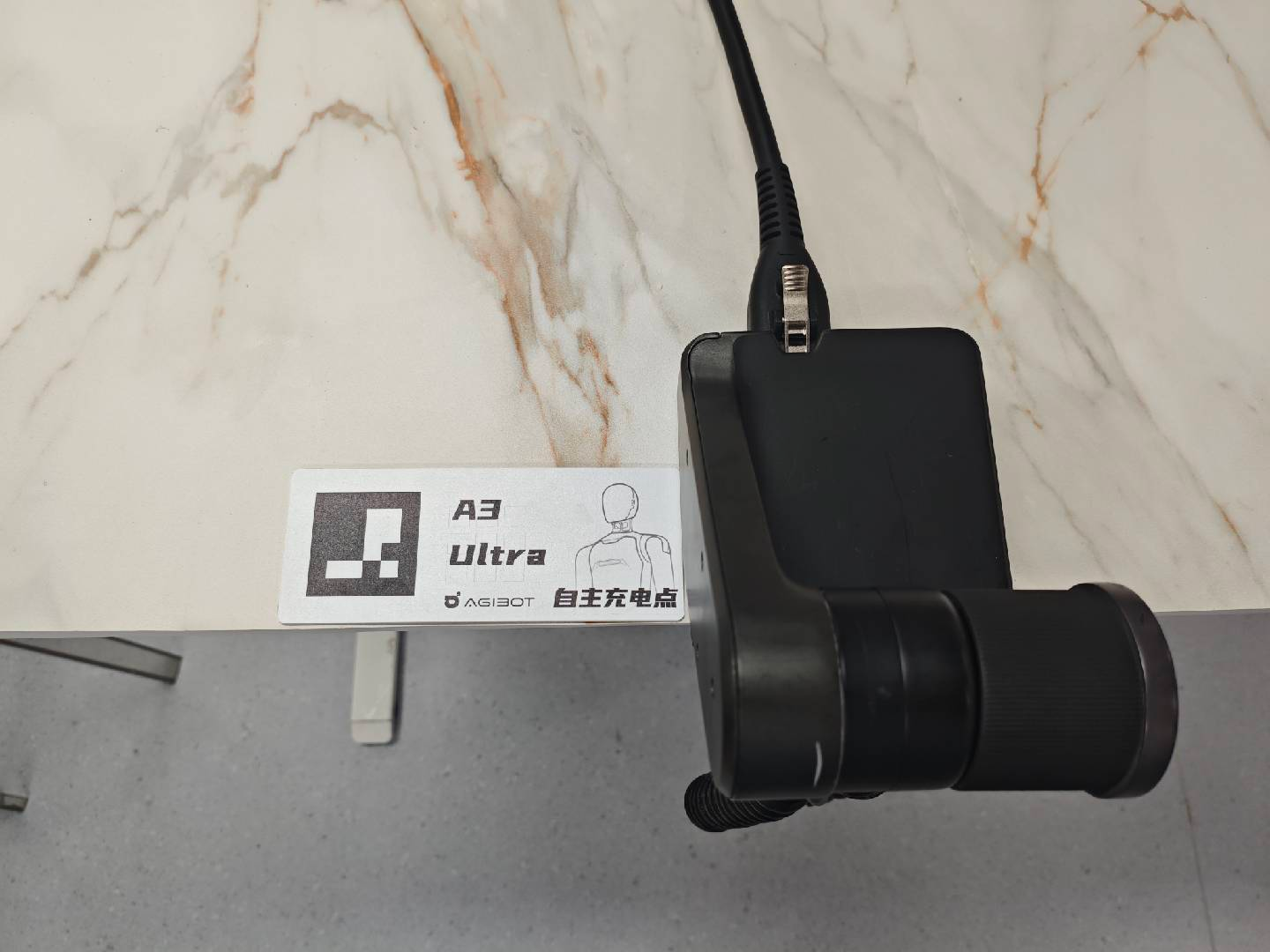
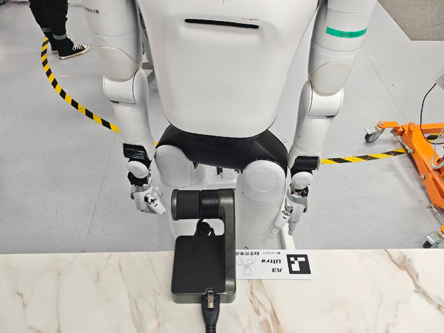
4. Open the AimMaster map page and select Edit Map.
5. Select Point → Record → Charging Point in turn. The live feed from the robot's chest camera appears in the upper-left corner, and the dashed box in the lower-right corner indicates the best deployment position for the charging gun.
6. Fine-tune the robot's position with the controller or by dragging until the charging gun is inside the dashed box; the dashed box turns green once the charging gun is detected.
7. Tap Charging Point → Mark, name the charging point, and tap Save to finish creating it.
○ Note: The charging point can be given a custom name; this does not affect how the function is triggered.
8. Only one charging point can be created per map. To change the charging point location, delete the current charging point first and then create a new one.
4.5.3.2.2 Enabling Autonomous Charging
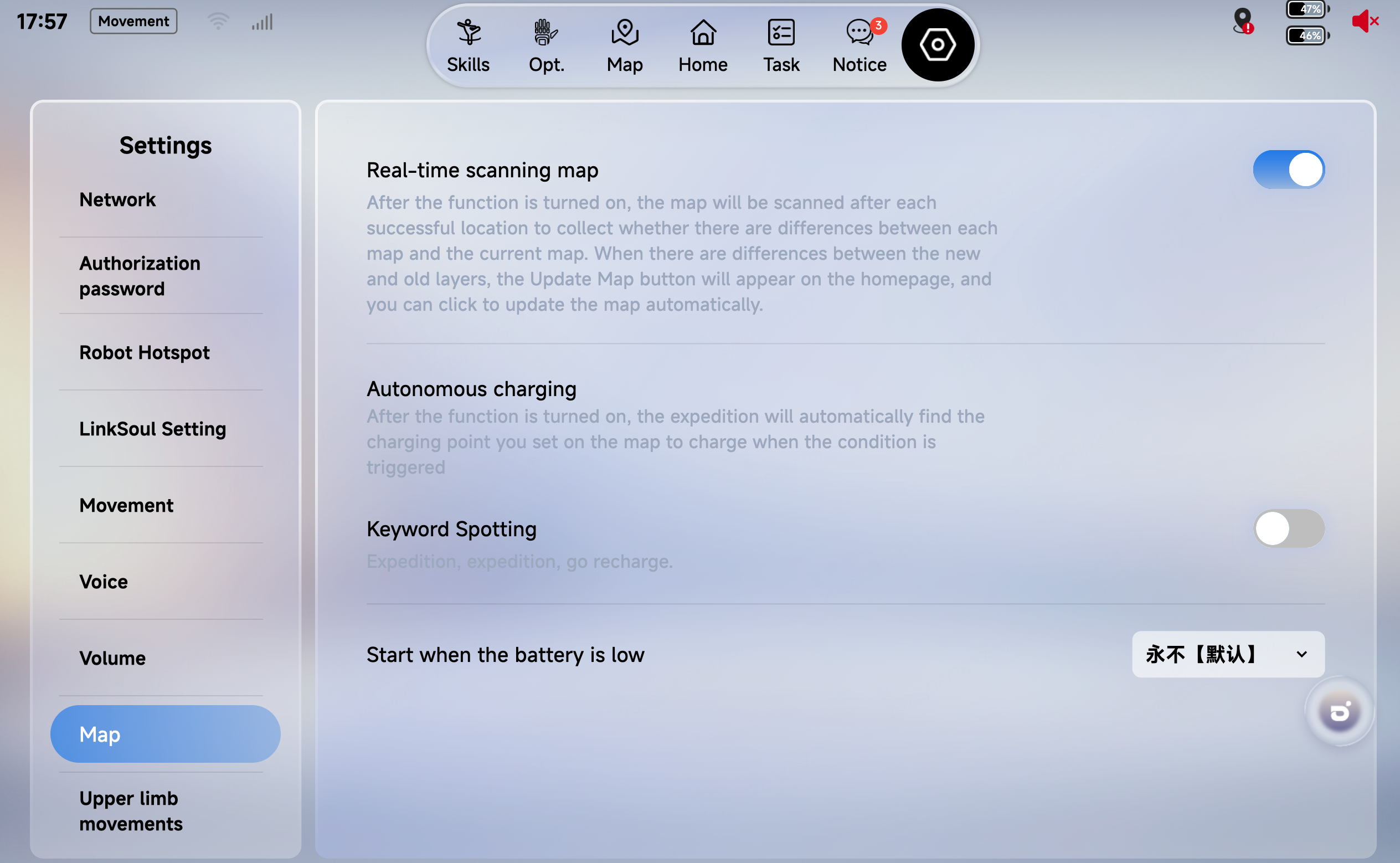
1. Autonomous charging can be enabled on the Settings → Map page.
2. Two trigger methods are available: voice trigger and low-battery trigger.
○ With voice trigger enabled, autonomous charging can be triggered by the voice command.
○ For the low-battery trigger, you can choose a threshold of 20%, 30%, 40%, or 50%; autonomous charging is triggered when the battery level falls below the selected threshold.
4.5.3.3 Autonomous Charging
4.5.3.3.1 Starting Autonomous Charging
Preconditions for normal triggering: The robot is not executing any task other than Lively Standby; a charging point exists on the current map; the robot's localization is normal and the robot is in a movable state. |
Trigger Method | User Operation |
Voice trigger | Say "Luka Luka, go charge" or "Luka Luka, go to the charging point" |
Automatic low-battery trigger | Triggered automatically when the battery level falls below the configured threshold |
4.5.3.3.2 Ending Autonomous Charging
Exit Method | User Operation |
Voice exit | Say "Luka Luka, end charging" or "Luka Luka, stop charging" |
Manual exit from the client | Tap End Charging Task in the client |
Full-battery exit | No operation needed; triggered automatically when the battery level exceeds 95% |
4.5.3.3.3 Interrupting Autonomous Charging
Condition for ending autonomous charging: Both batteries are correctly installed and the battery level is ≥ 15%. Otherwise, the robot cannot exit charging autonomously. |
Phase | Can Be Interrupted | How to Interrupt |
Navigation | Yes | Voice command; terminate the task in the client |
Plugging in the gun | No | Not supported |
Charging | Yes | Voice command; terminate the task in the client |
Unplugging the gun | No | Not supported |
4.5.3.4 Troubleshooting Quick Reference
Symptom | Possible Cause | Solution |
Autonomous charging cannot be triggered | Trigger method not enabled; no charging point set (or wrong charging point name); localization abnormal; robot not movable; or another task in progress | Check the settings, map localization, and robot status; trigger again after other tasks finish |
Cannot reach the charging point | Path blocked by people, objects, or temporary obstacles | Clear the path, exit the current task in the client, and trigger autonomous charging again |
Charging gun not recognized | Charging gun in the wrong position, outside the dashed box, occluded, or abnormal lighting | Adjust the charging gun position; make sure it is unobstructed and lighting is normal |
Plugging, unplugging, or holstering the gun fails | Charging gun position offset; QR code position offset; arm path blocked; cable under tension | Do not forcibly pull the arm or cables; wait until the robot's arms return to its sides, then manually help the robot plug in, unplug, or holster the gun |
4.5.3.5 Precautions
Precautions 1. Before triggering autonomous charging, make sure both batteries are correctly installed and the battery level is at least 5%. Otherwise, insufficient power may prevent the robot from completing the charging process or cause it to fall. 2. If the robot is in an abnormal state, emergency-stop state, or abnormal posture, restore the robot to a normal state before triggering autonomous charging. 3. Do not move the deployed charging table, charging gun, or charging base at will. If their positions change, check and update the charging point again. 4. During autonomous charging, do not cover the QR code on the table, as this affects recognition and plug/unplug success rate. 5. During autonomous charging, do not cover the robot's cameras, the charging gun, or the charging base, as this affects recognition and plug/unplug success rate. 6. Do not reach in while the robot is plugging in / unplugging the gun. If the operation fails, wait until the robot's arms return to its sides before attempting to recover. 7. If the robot fails to plug in the gun autonomously, manual assistance is required. After manually assisting the plug-in, the robot cannot exit this charging task autonomously. 8. After each charging task, make sure the charging gun is correctly returned to the base. If the robot fails to holster it, return it manually; otherwise the next autonomous charging task cannot start. 9. The entire autonomous charging process cannot be interrupted by other tasks. Do not launch other tasks while autonomous charging is running. |
4.6 Emergency Stop Function
The emergency stop function is used for the emergency stop of the robot in case of sudden situations, preventing further damage to the robot or the surrounding environment, and can be triggered in the "Soft Emergency Stop" mode.
After the robot enters the emergency stop state, its limbs will lose power and fall to the ground, with a certain risk of damaging the machine. Please ensure that users use the emergency stop function with extreme caution.
4.6.1 Triggering the Soft Emergency Stop
1. Steps to trigger the emergency stop state
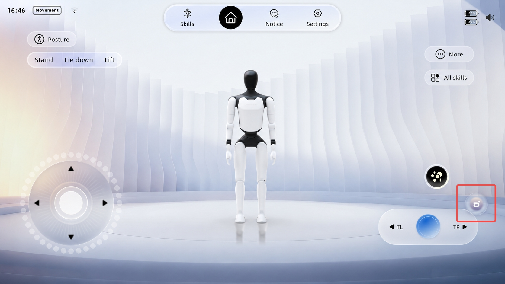
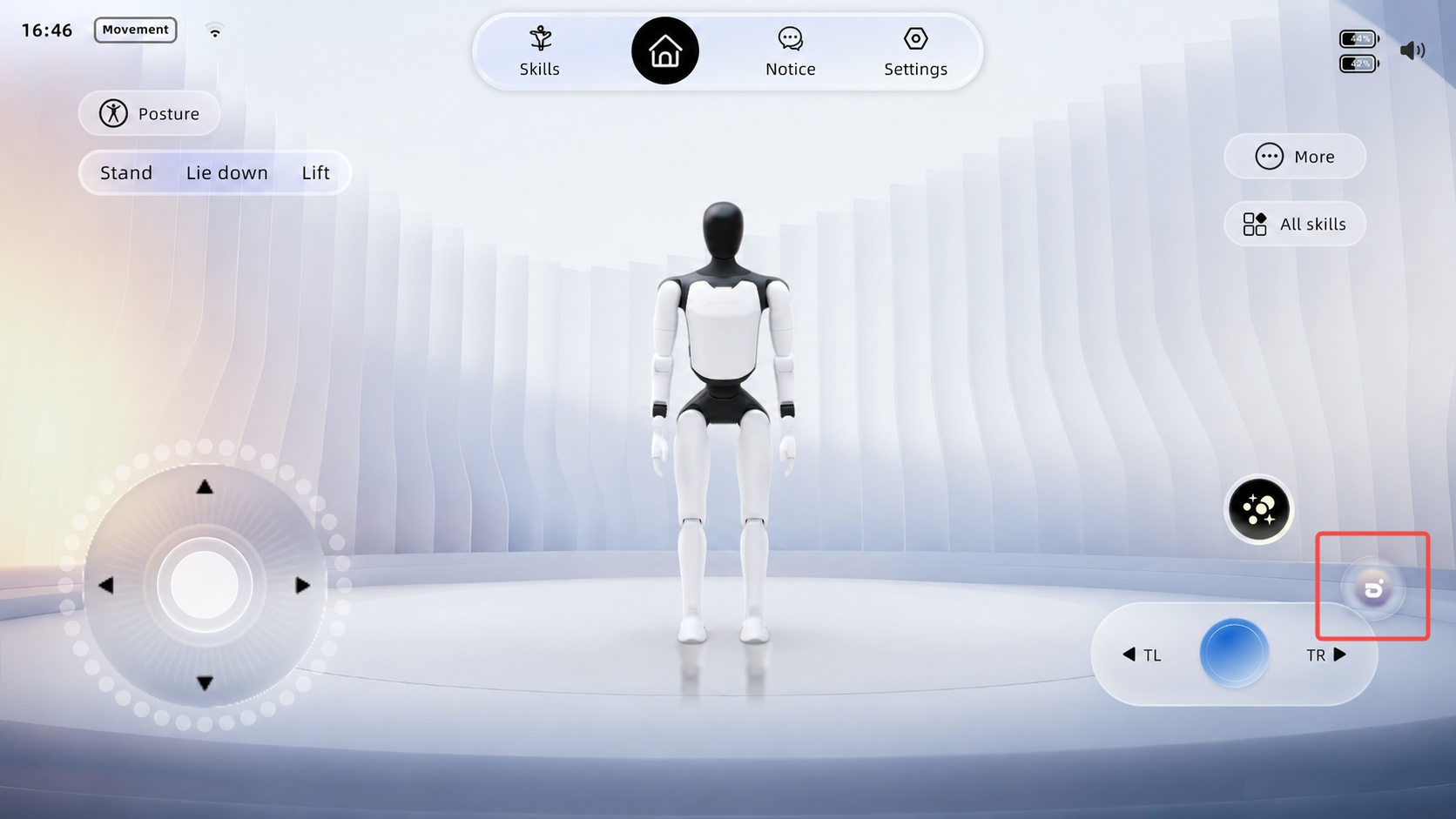
Method 1: Triggered via AimMaster
Operation Steps | Operation Interface |
Press the floating ball to enter the emergency stop page |
|
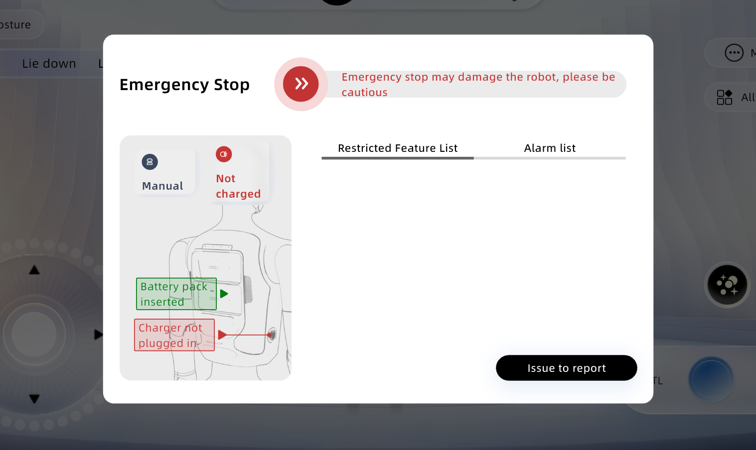
Press and hold the [Emergency Stop] button, then slide it to the right until it reaches the end to trigger a soft emergency stop |
|
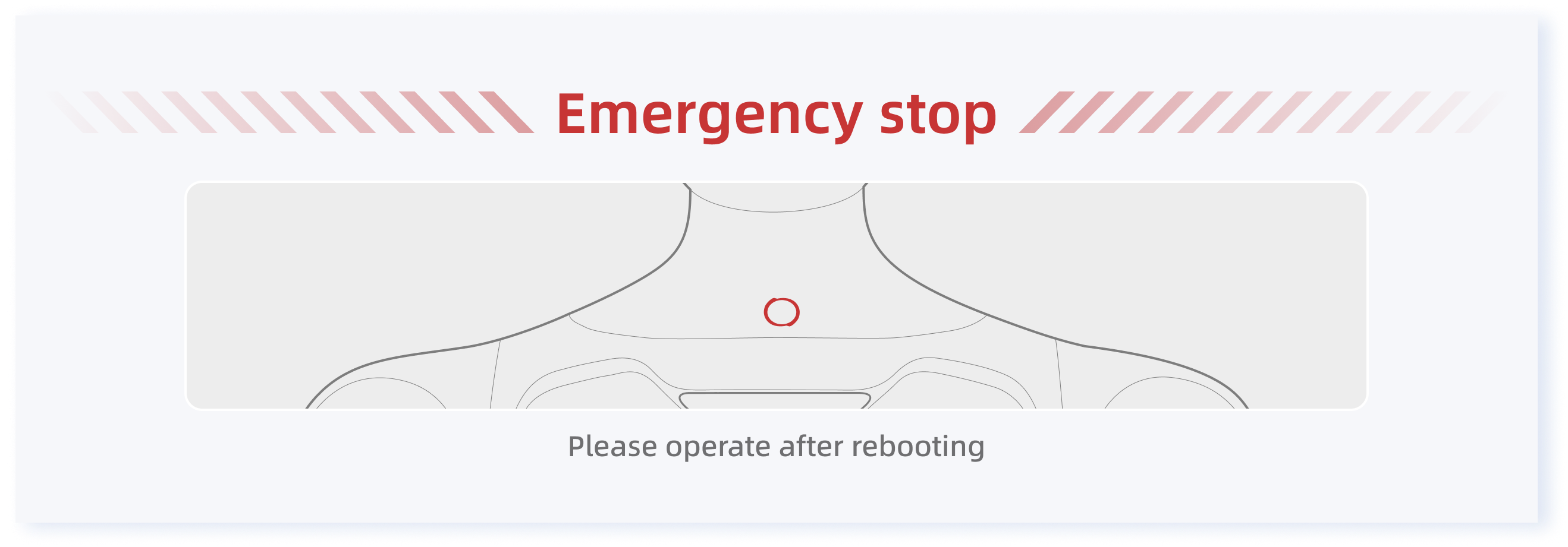
Enter the soft emergency stop state |
|
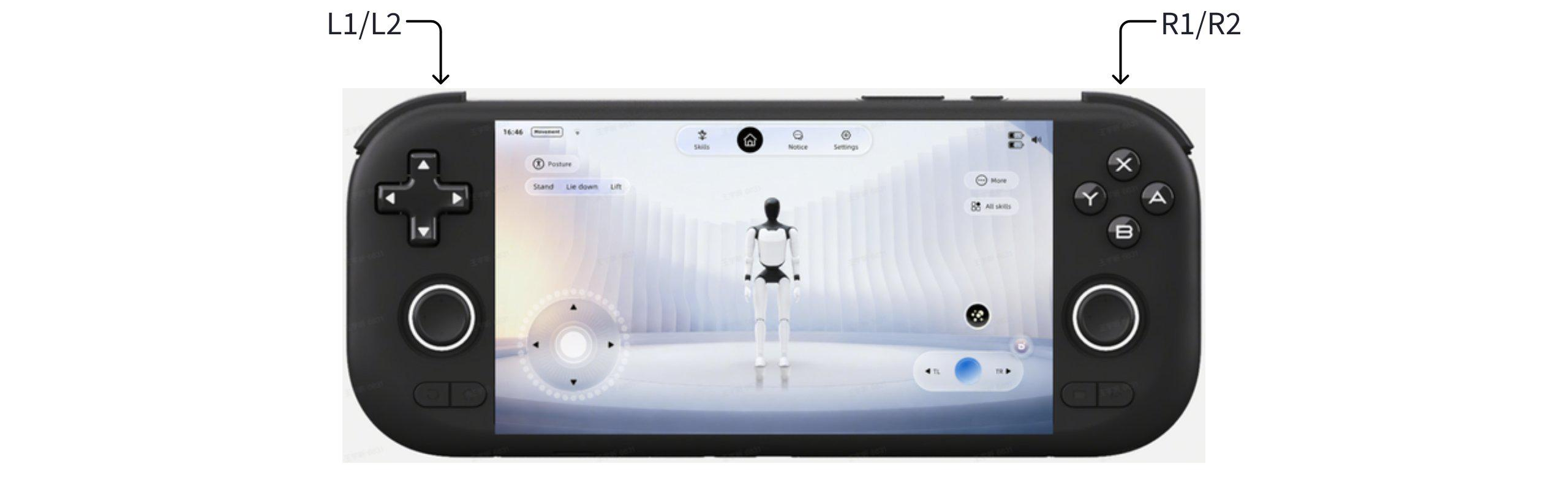
Method 2: Triggered by remote control buttons (applicable to remote controls)
When the remote control is connected to the robot, hold the four buttons L1+L2+R1+R2 at the same time for more than 0.5 seconds to trigger the soft emergency stop state.
2. Operable items in the soft emergency stop state
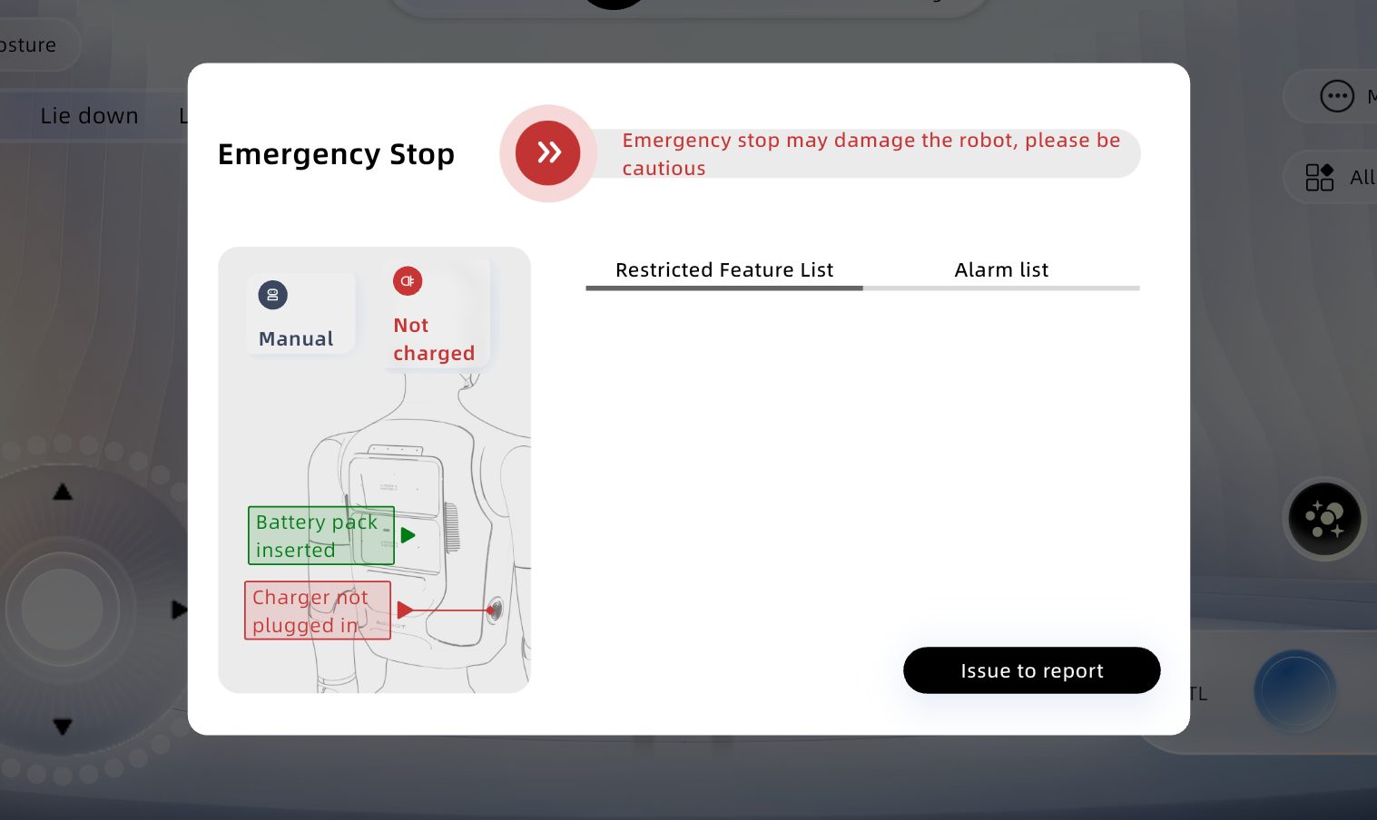
After the robot enters the soft emergency stop state, only limited operations such as viewing the function list and alarm information, and reporting problems, can be performed on the floating ball page.
Operation Steps | Operation Interface |
Tap the floating ball |
|
Limited operations such as viewing the function list and alarm information, and reporting problems, can be performed |
|
3. Steps to exit the soft emergency stop state
Restart the robot to exit the soft emergency stop state.
4.6.2 Emergency Stop Settings
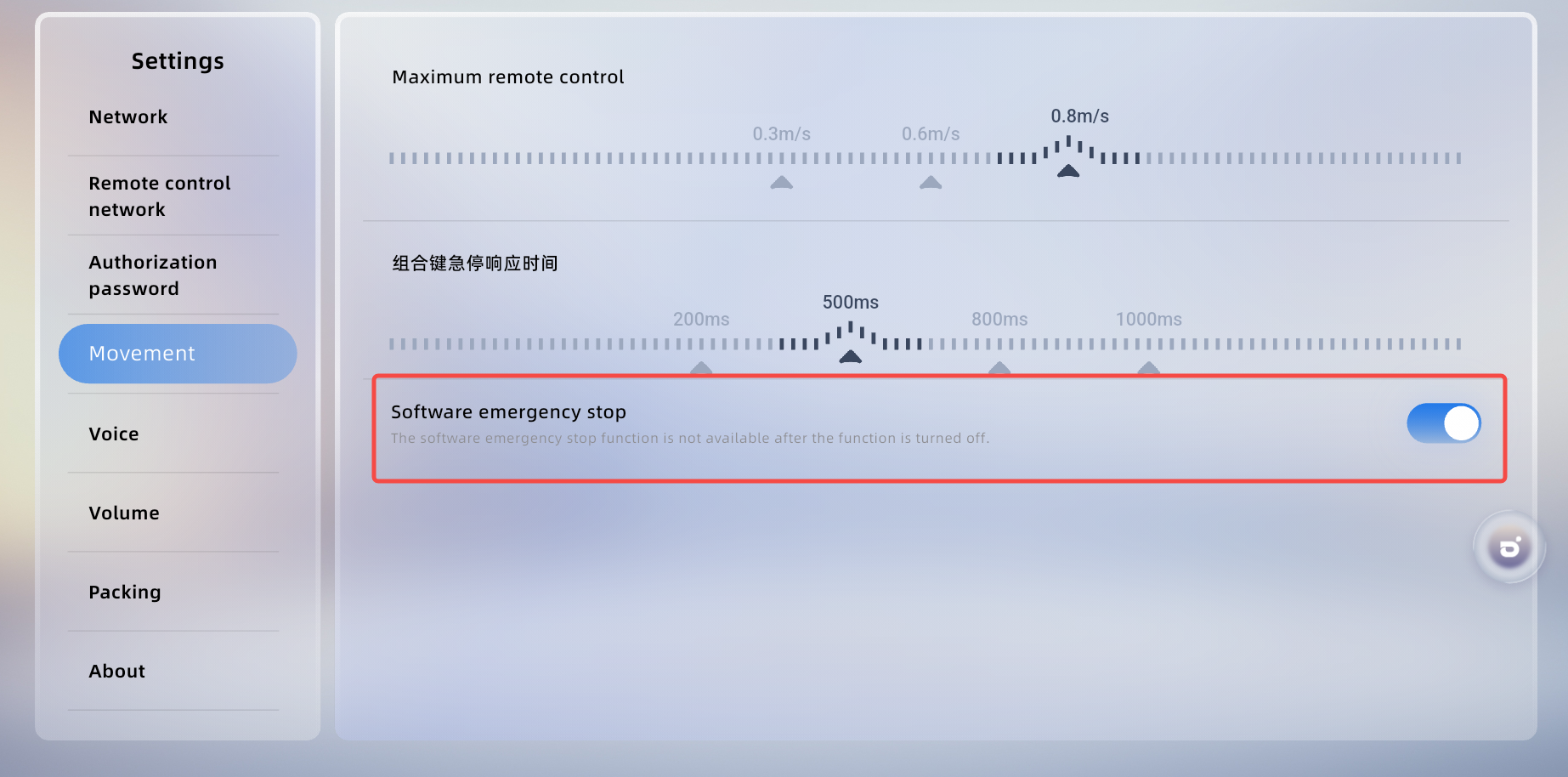
Turn on/off the soft emergency stop function: On the [Settings] - [Movement] page of AimMaster, you can turn the software emergency stop function on and off.
4.7.1 Remove the Silicone Hand
Step 1: Power off the robot and remove all batteries and charging plugs (this step must not be skipped; otherwise there is a safety risk).
Step 2: Remove the silicone strip above the dummy hand to expose the screws on the dummy hand.
before removal :
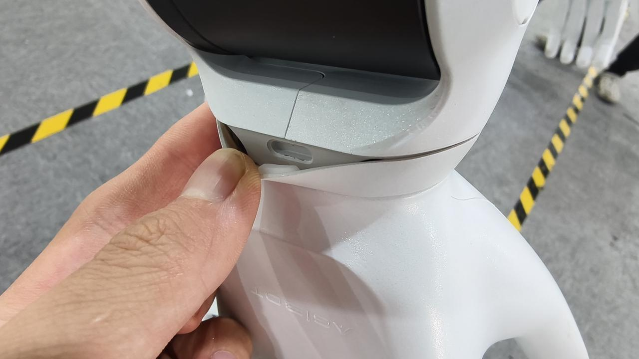
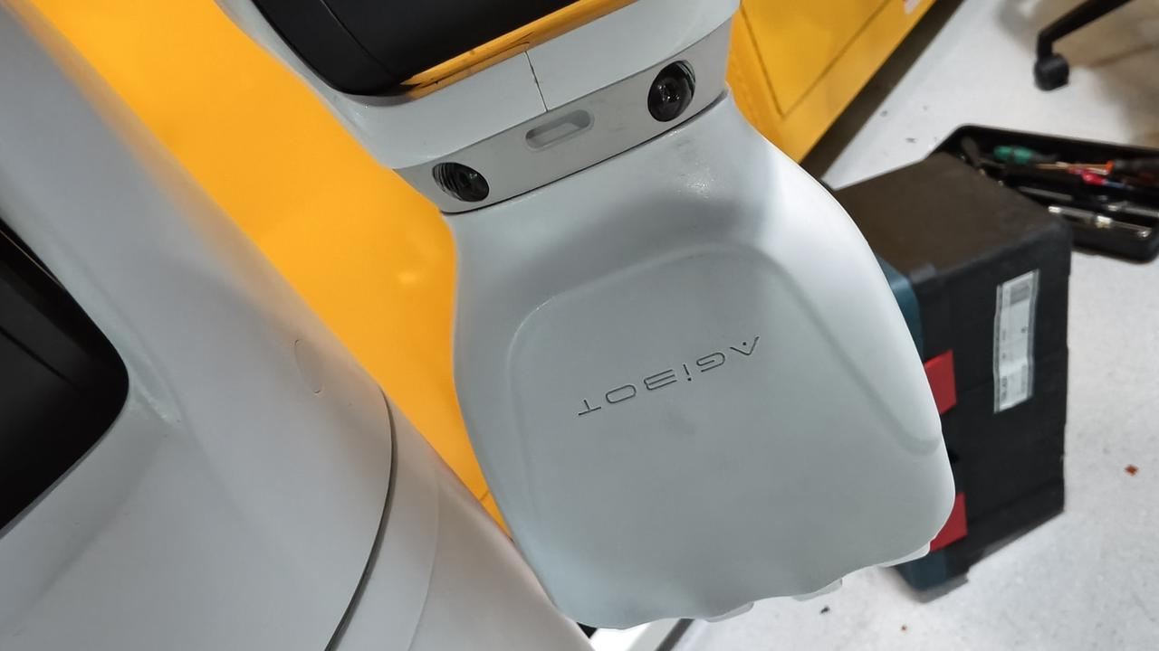
after removal:
Step 3: Remove the four screws securing the dummy hand (two at the front, two at the rear).
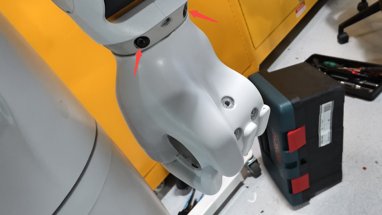
The dummy hand can then be removed
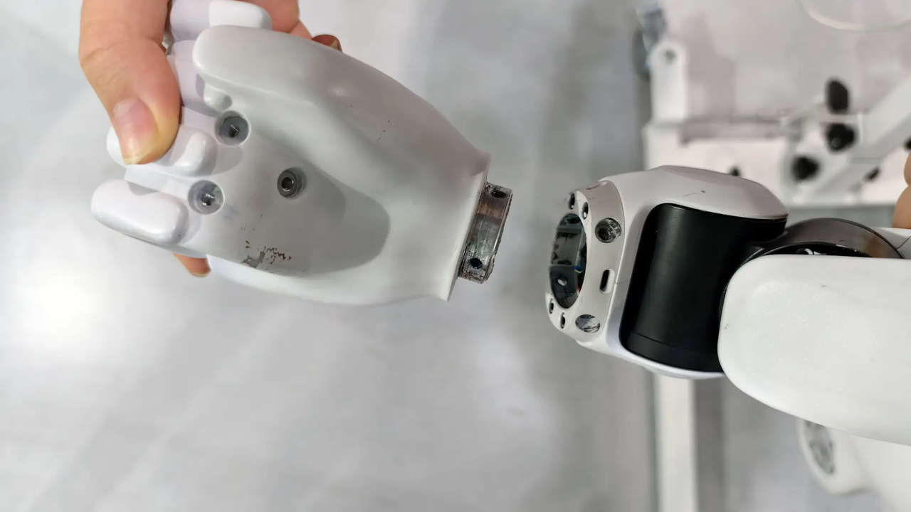
Step 4: Remove the terminal resistor on the wrist harness connector (keep the terminal resistor safe; it must be reinstalled when switching back to the silicone dummy hand).
|
|
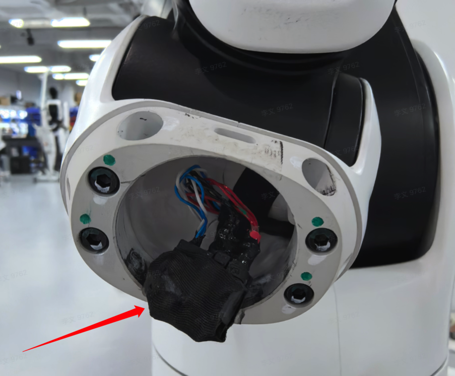
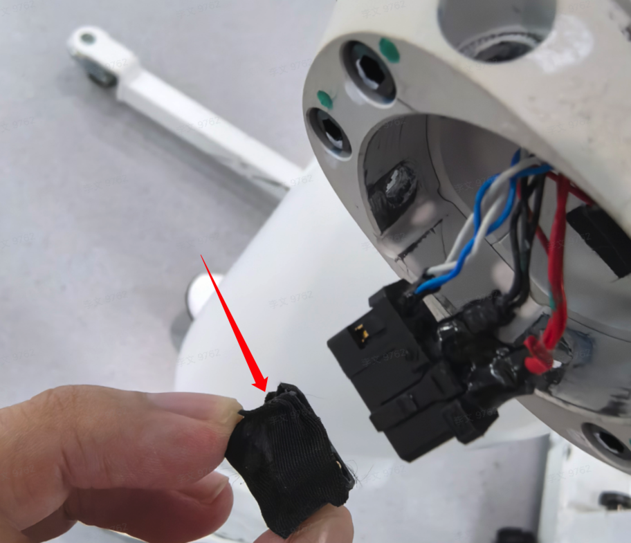
4.7.2 Install the Dexterous Hand
Step 1: Align the wrist harness connector and insert it into the socket inside the dexterous hand (the connector has a fool-proof design; align it correctly before pressing it in — never force it).
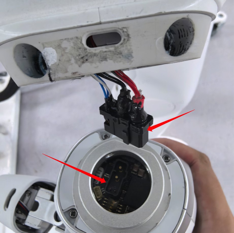
Step 2: Align the dexterous hand with the forearm and join them together; install the four screws (front and rear), then put the original silicone strip back in place.
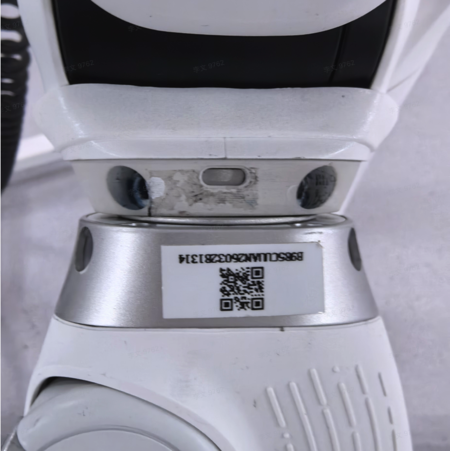
4.8 Replace the Silicone Hand
4.8.1 Remove Silicone Hands (a screwdriver is required; the screwdriver is provided in the accessory kit)
If a dexterous hand is being removed, power off the robot and remove all batteries and charging plugs first. |
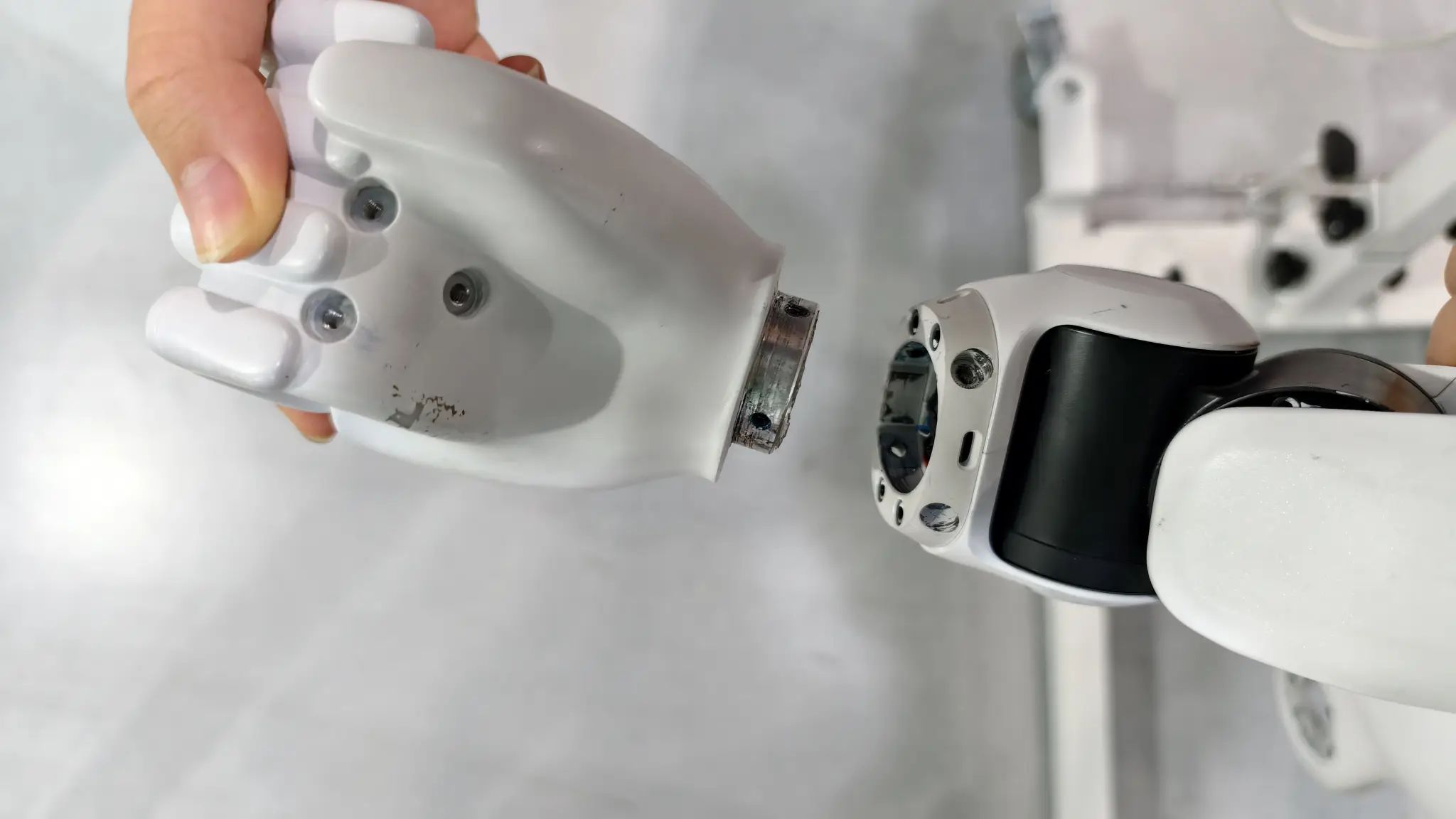
4.8.2 Install Silicone Hands
Step 1: Check that the terminal resistor is properly installed
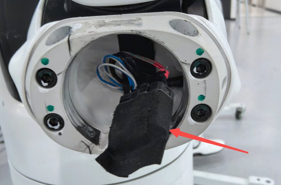
Step 2: Align the silicone hand with the forearm and join them together
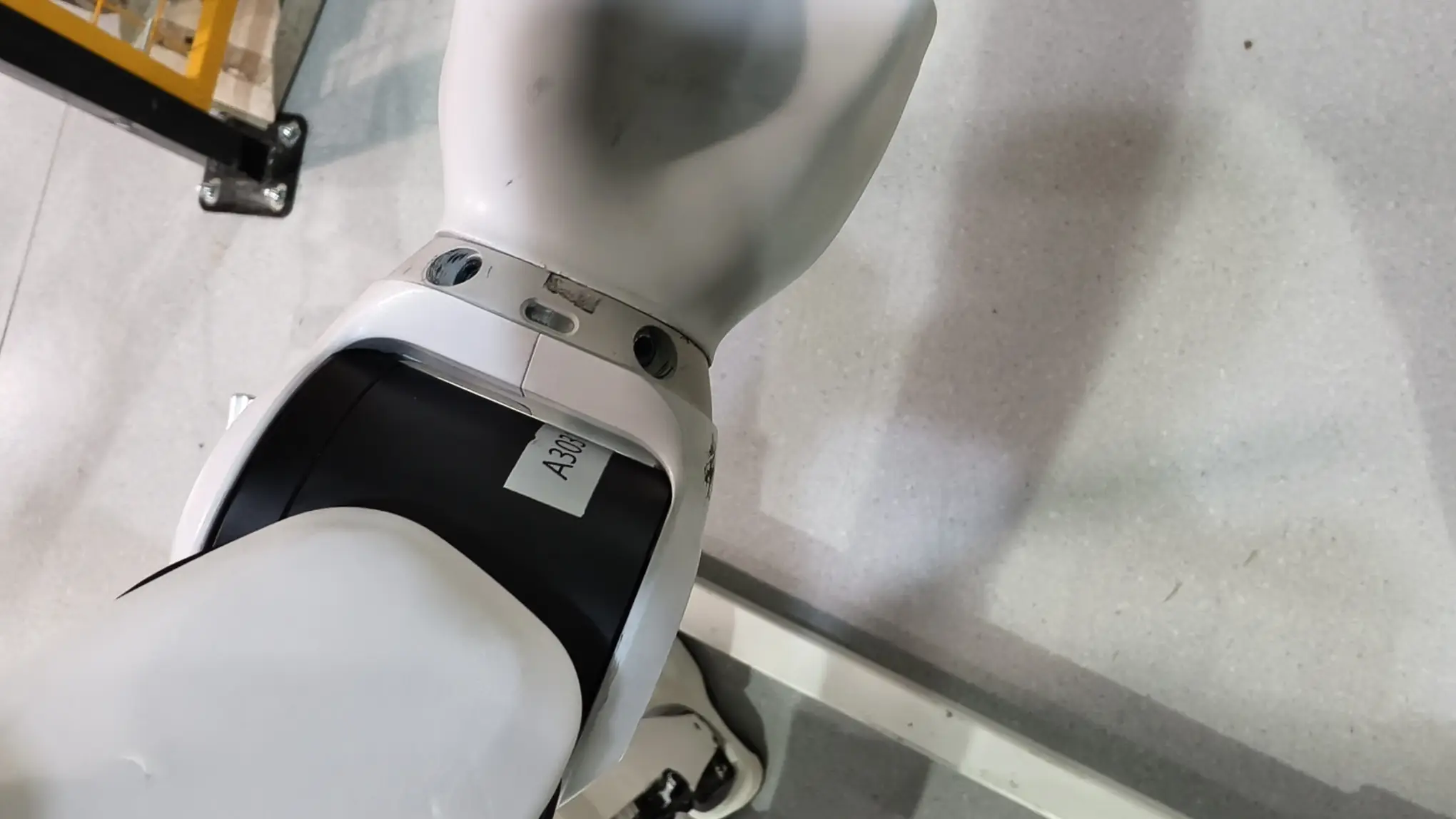
Step 3:Install a total of four screws, front and rear
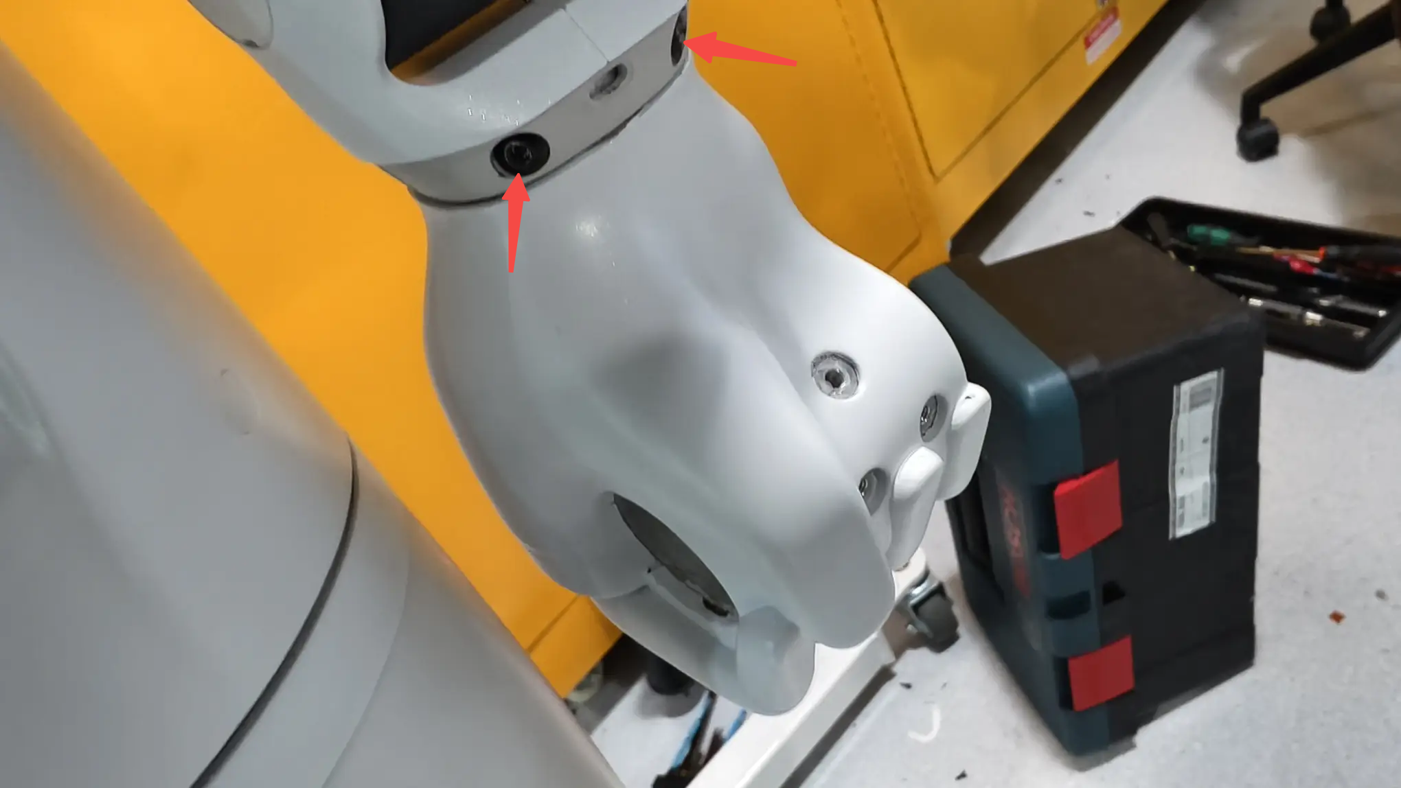
Step 4: Place the silicone strip according to the position to cover the four screws
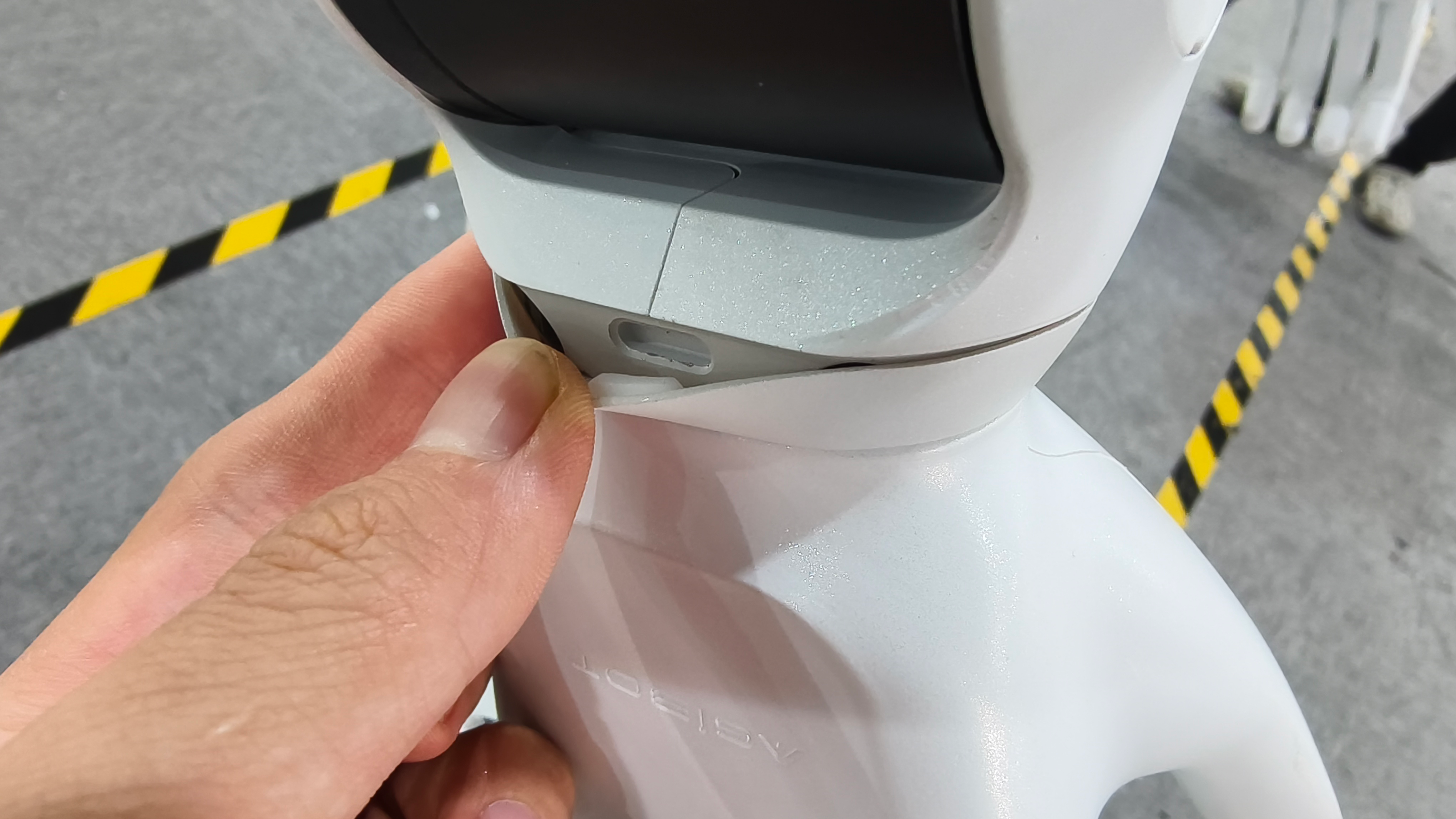
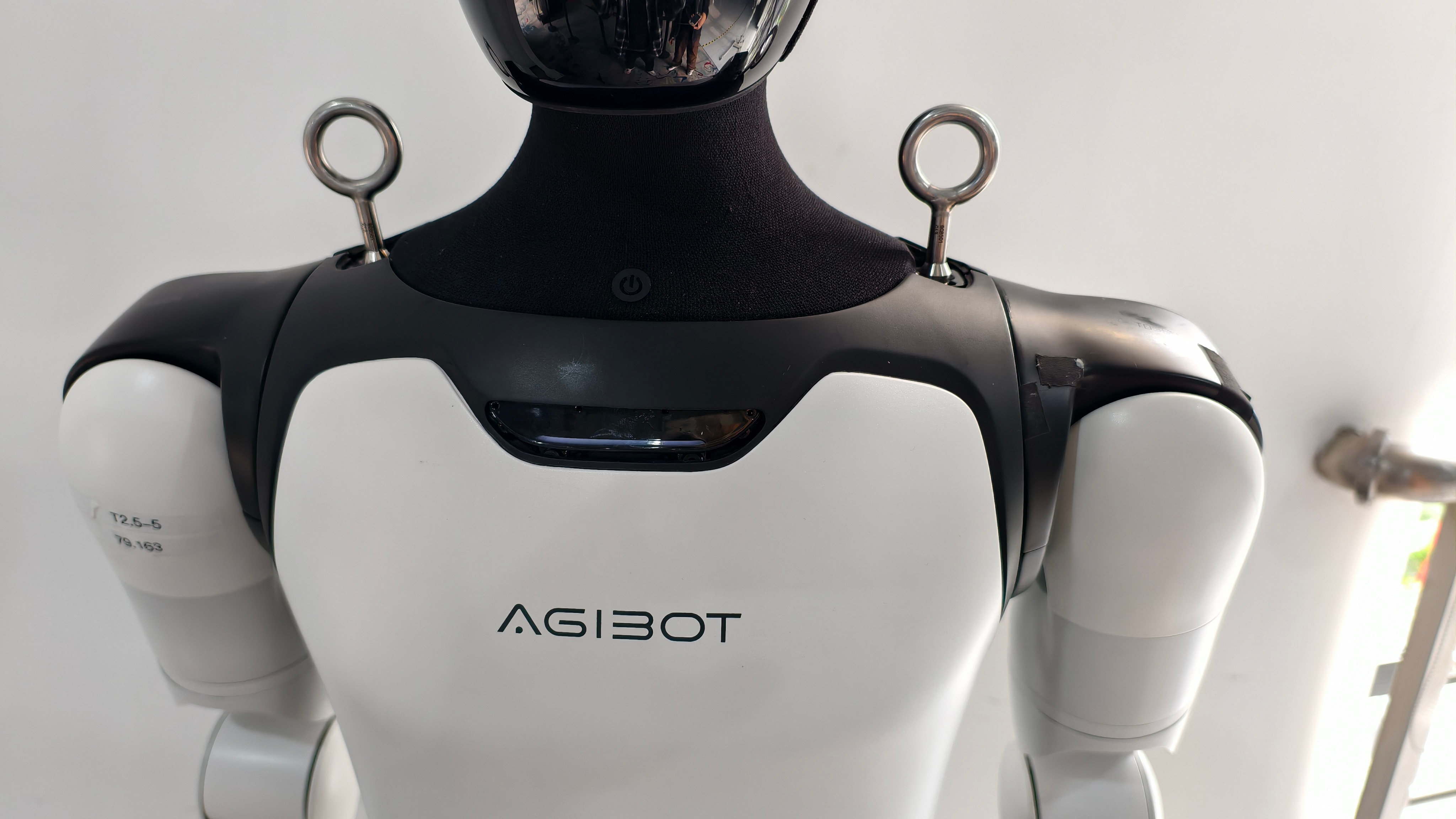
4.9 Lifting Ring Installation
• Step 1: Pull out the rubber plugs on both shoulders of the robot to expose the mounting slot
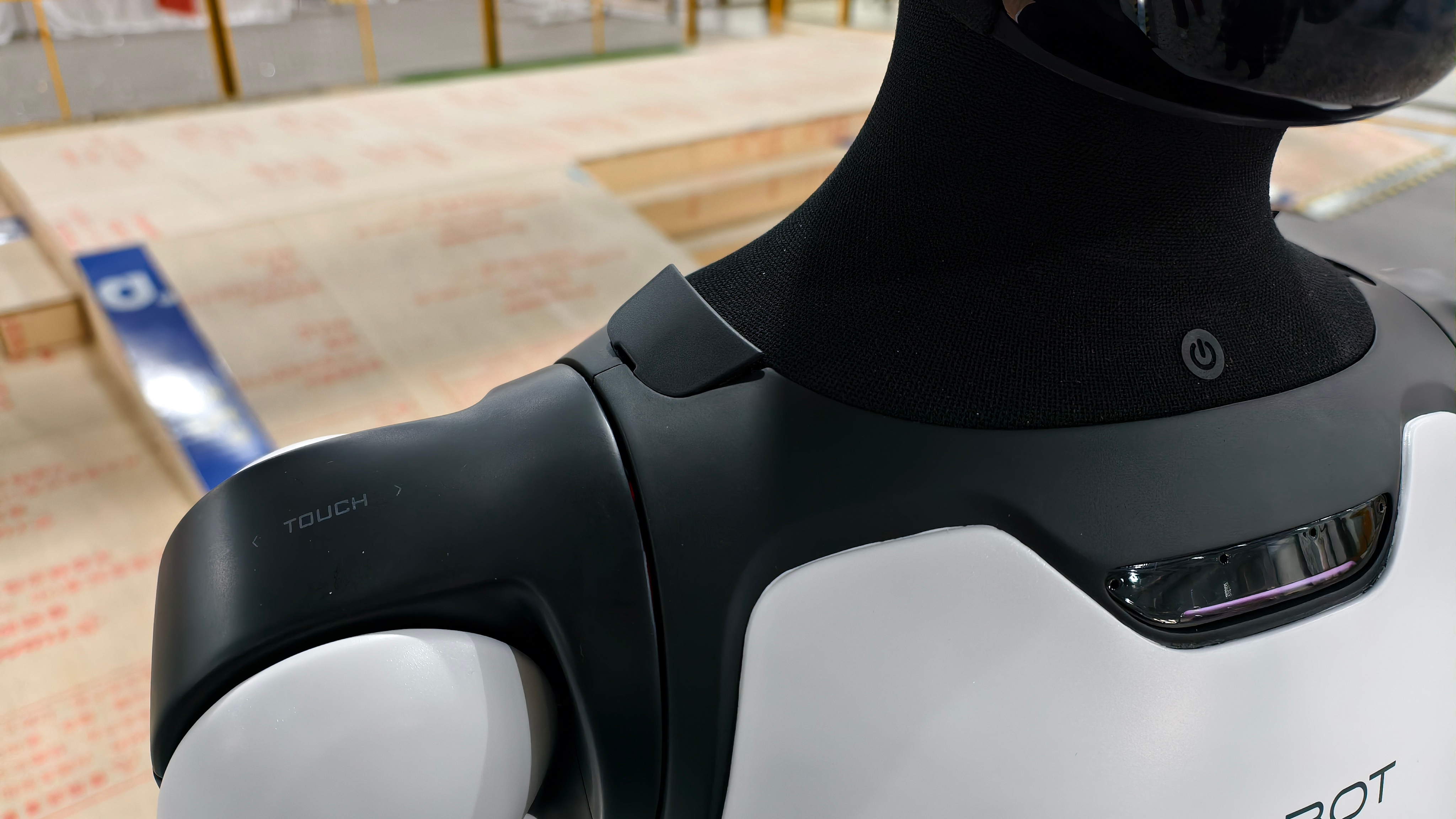
• Step 2: Hold the ring end and align the buckle end with the slot and press it firmly
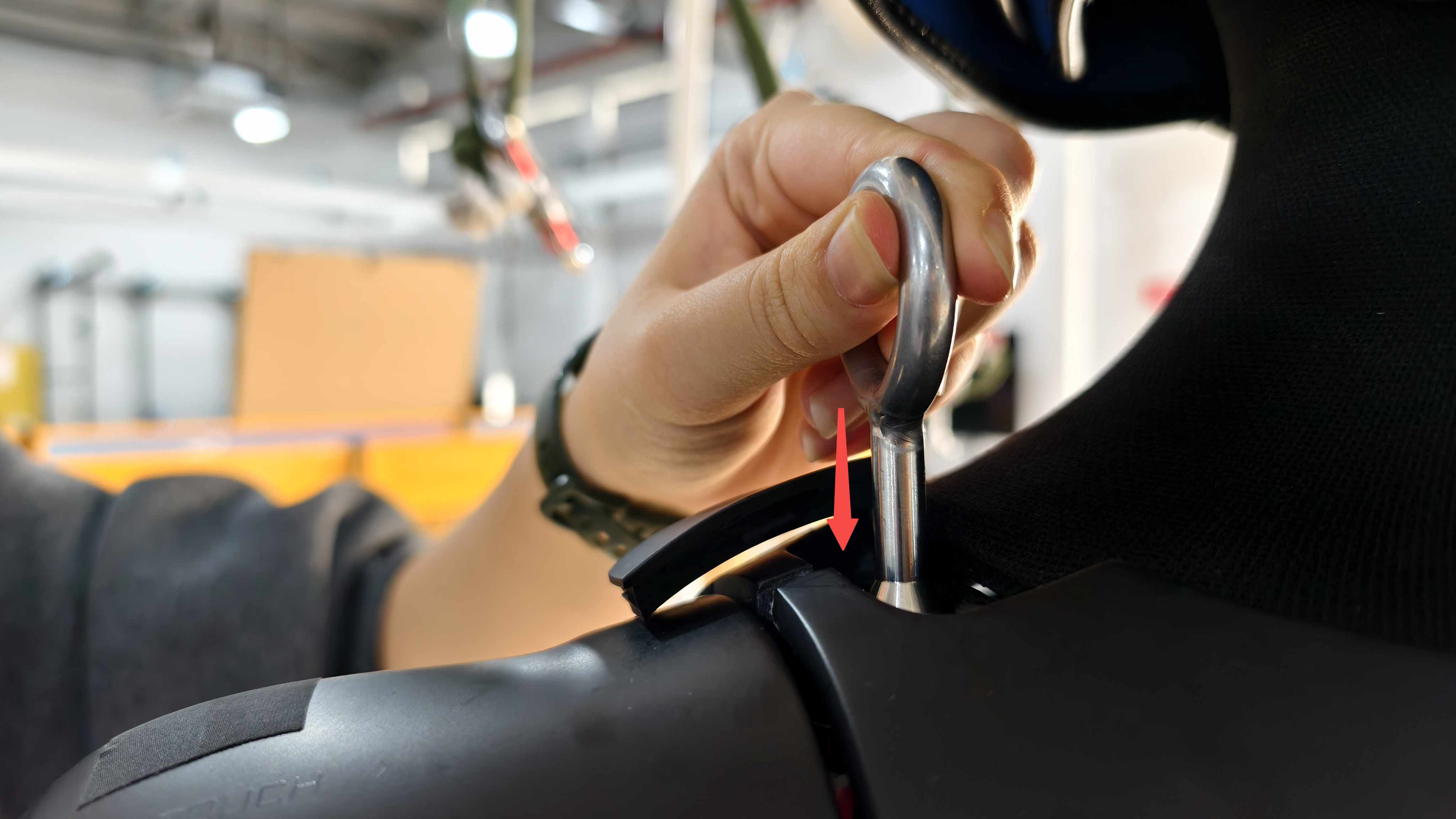
• Step 3: Rotate the lifting ring 90° and leave it there
5. Function Description
5.1 Full-Body Dance
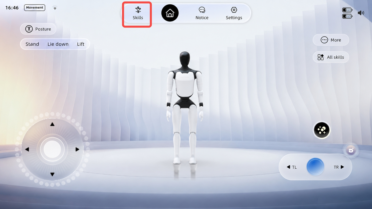
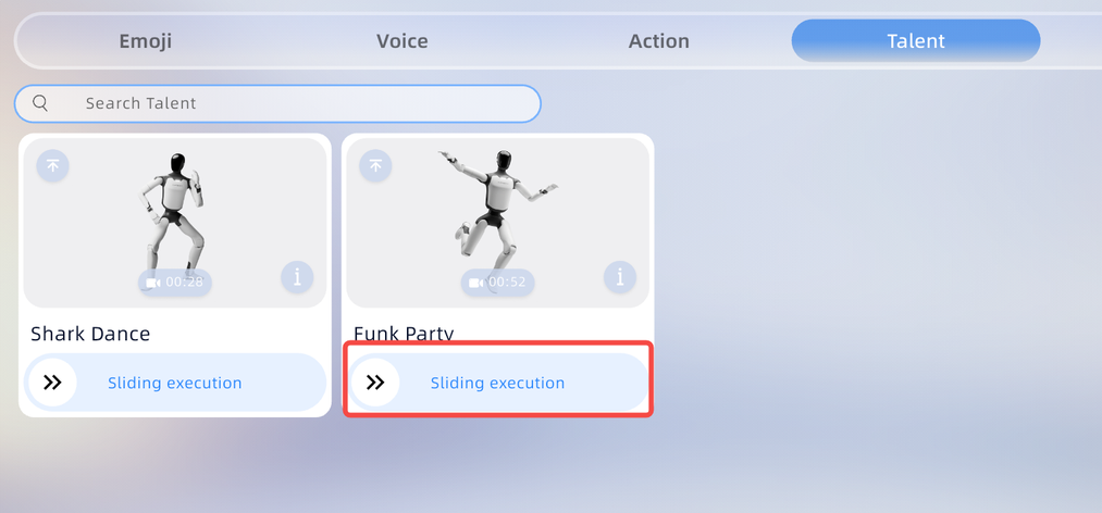
In the Talent screen of the skill operation navigation bar, select the corresponding dance content and swipe to play.
Step 1: Tap the top tab bar and select [Skills]
Step 2: Select the desired dance, and swipe to execute
Note: Different dances must be confirmed and executed according to their respective pop-up instructions. Follow the prompts to ensure safety. |
5.2 Body Actions
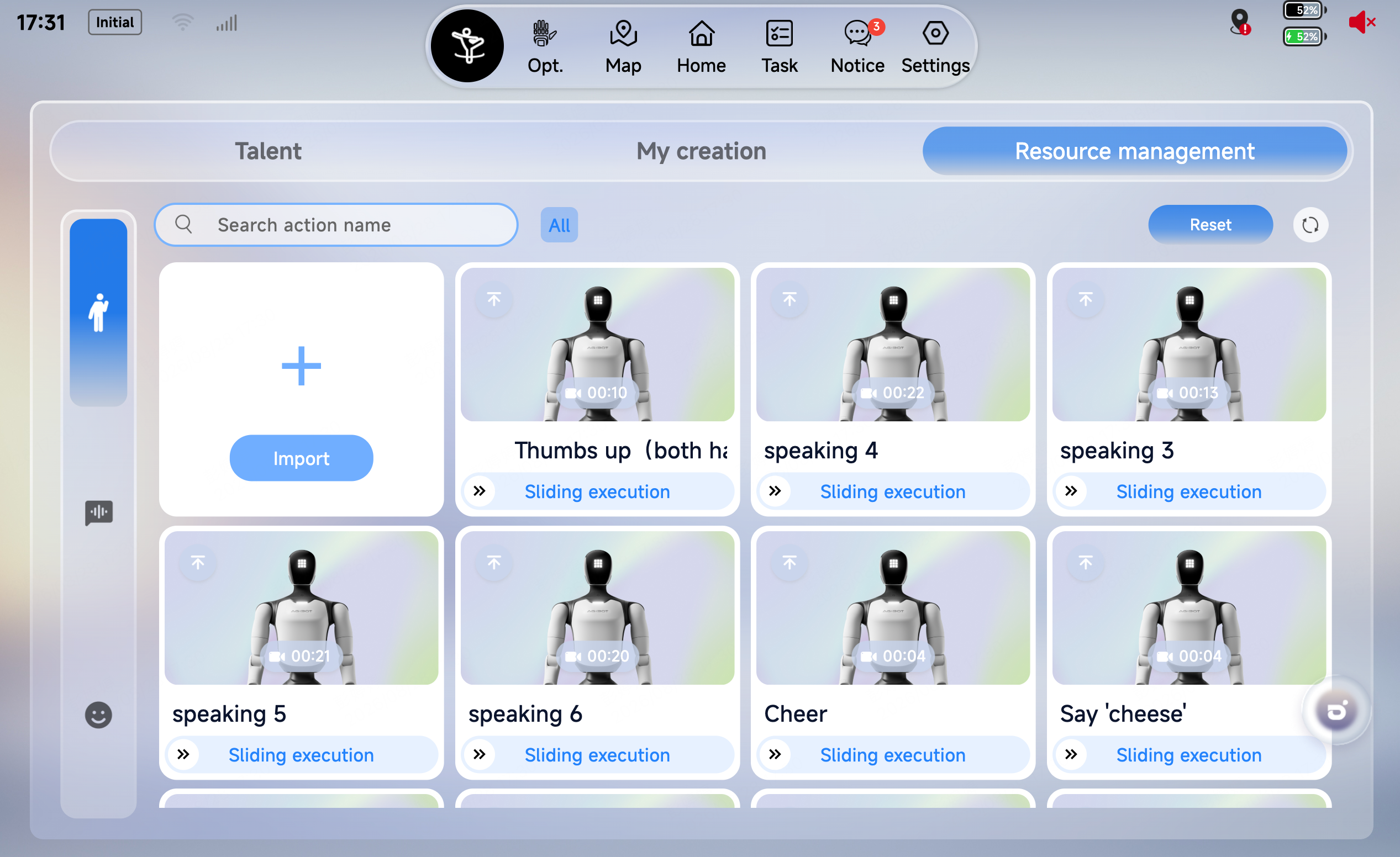
5.2.1 Upper-Limb Actions
On the client home page, tap Skills > Resource Management, then select an action to play.
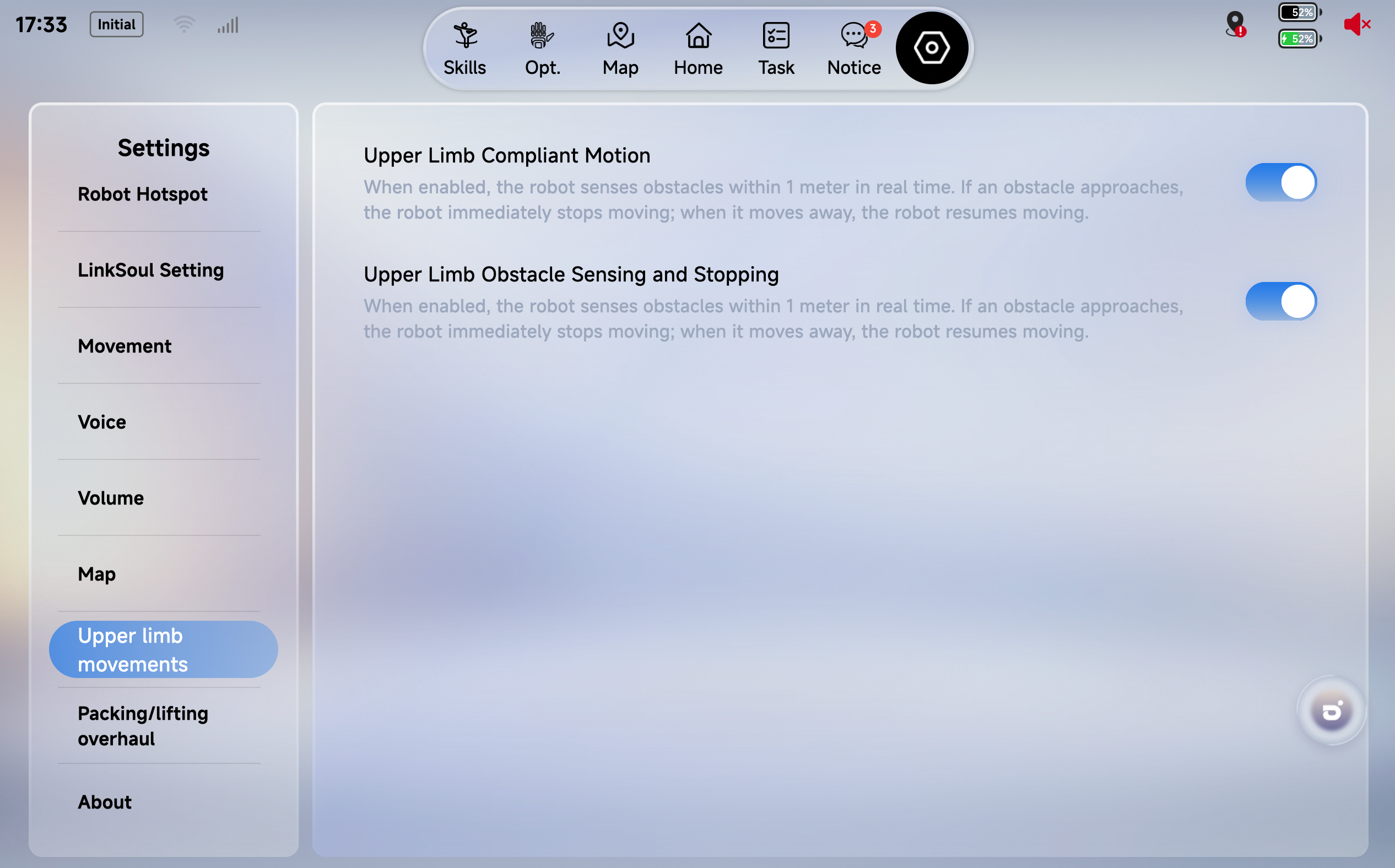
5.2.2 Upper-Limb Compliant Motion Playback (Passive Safety)
When this switch is turned on, the robot's arms become compliant, which reduces collision force.
5.2.3 Upper-Limb Motion Perception-Based Obstacle Stop (Active Safety)
When this switch is turned on, if you stand within the range of the robot's motion, the arm will pause for your safety (staying within 20 cm of the robot may affect the obstacle-stop performance).
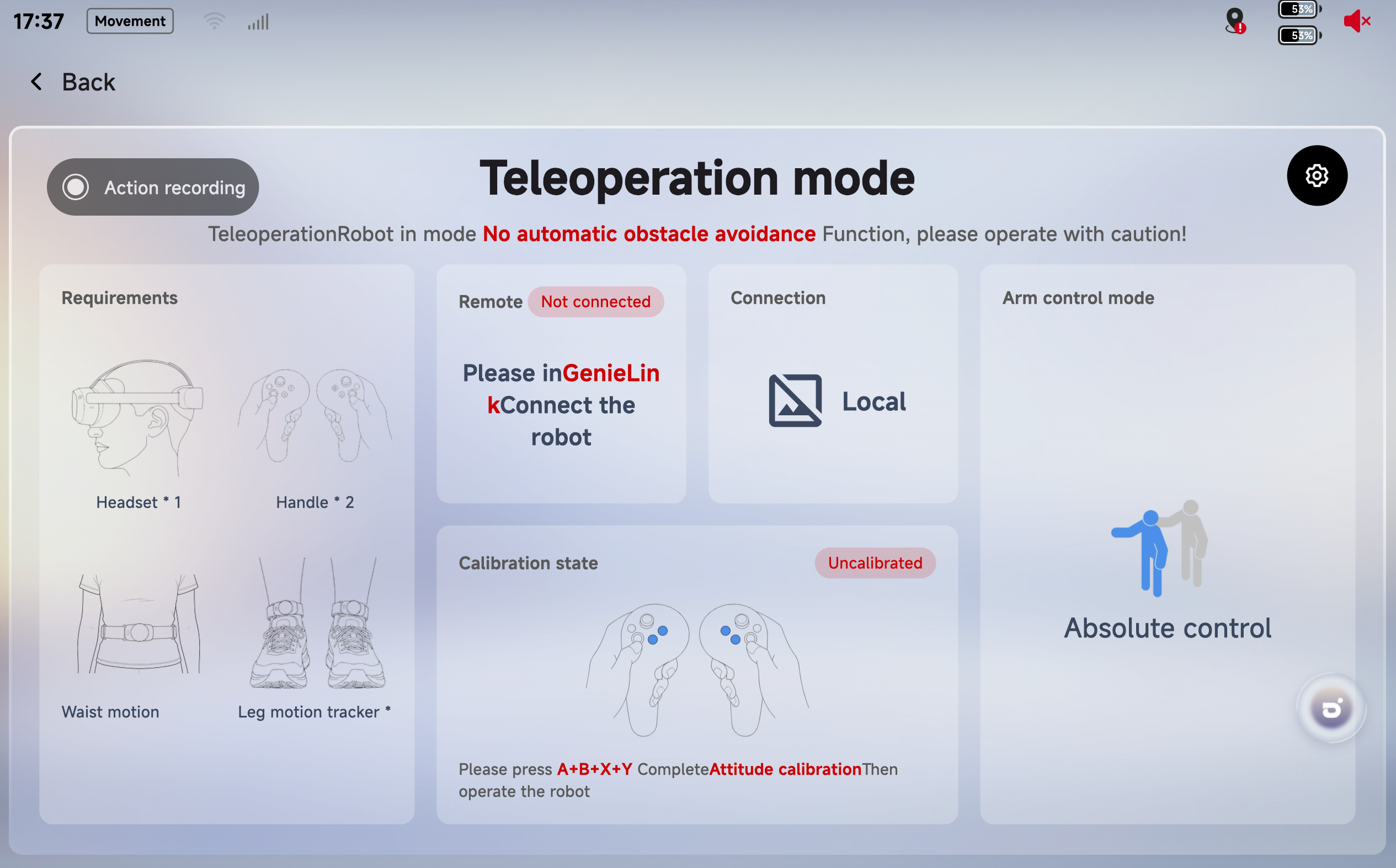
5.2.4 VR Motion Recording Supported on the Client
After you complete teleoperation calibration and take over the robot, press the [Action Recording] button to start recording.
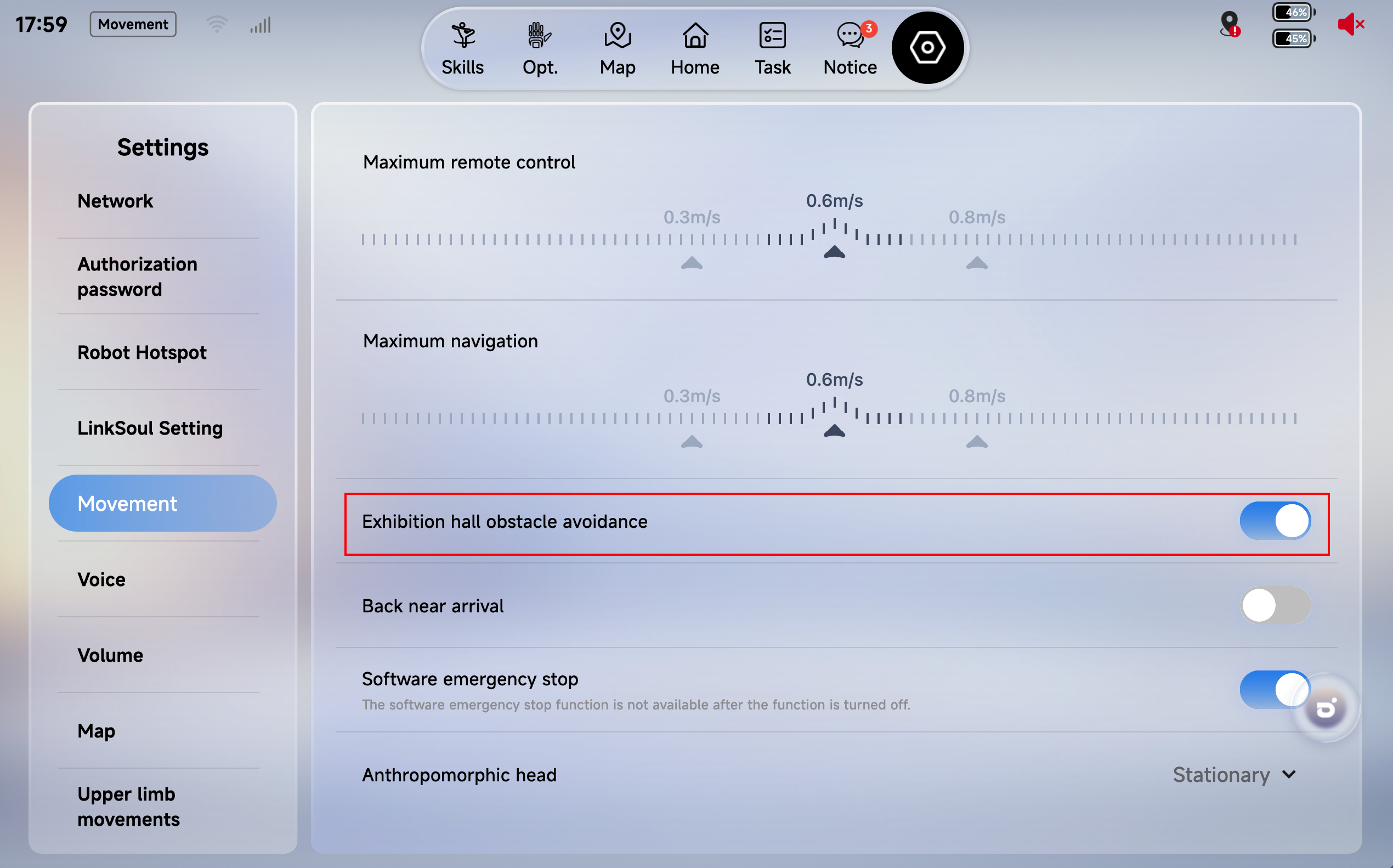
5.3 Navigation and Obstacle Avoidance
The switch is on by default. Once you turn it off, the robot will no longer avoid obstacles, posing a collision risk — please use this option with caution.
5.4 Lively Standby
The [Lively Standby] switch is off by default. It can be enabled under [Settings] > [Upper-Body Actions] > [Lively Standby] in AimMaster.
5.5 Robot Interaction
1. Two voice interaction inputs are available: [Built-in Mic] and [External Mic], which can be switched in the voice settings on the client.
2. Voice control of motions, dances, walking, and volume is supported, for example "Please shake hands", "Give me a dance", "Walk forward", "Set the volume to half", and "Set the volume to 30".
3. Stranger-recognition greeting is supported. A custom greeting can be set under [LinkSoul Platform] - [Welcome Settings] - [Stranger Greeting].
4. Lively greeting based on a multimodal large model is supported. It can be enabled under [LinkSoul Platform] - [Agent Center] - tap [Welcome Settings] - enable Lively Greeting.
5. Custom greeting is supported. Under [LinkSoul Platform] - [Edit Agent] - [User Information], you can set a dedicated welcome greeting for different users.
6. A newly added mute / interaction-disabled expression layer design (top-left corner of the screen), plus two new immersive expressions: entering the out-of-body avatar and the out-of-body avatar's ultimate move.
7. Multilingual interaction is supported, covering 16 languages including Chinese, English, German, French, Spanish, Japanese, Korean, Portuguese, Italian, Arabic, Thai, Russian, Malay, Vietnamese, Indonesian, Kazakh, and Turkish. Except for Chinese and English, the recognition rate of the other languages is approximately 65%–85%.
8. Speaker recognition is supported. Based on sound-source localization and visual information, the robot achieves "look at whoever is speaking" — turning its head / waist / whole body toward the user — and "knows who is speaking": for users with face ID, A3 Ultra can politely address them by name during wake-up responses and LLM chats. In complex environments with medium-to-high noise and multiple people, occasional positioning errors may occur; the [Interaction Full-Body Follow] switch under Client → [Voice] can be turned off.
9. Additional features will be added in subsequent OTA updates. For details, refer to the release notes of each version.
5.6 Spatial Tasks
5.6.1 Mapping and Point Marking
1. Open the client and enter the Map module.
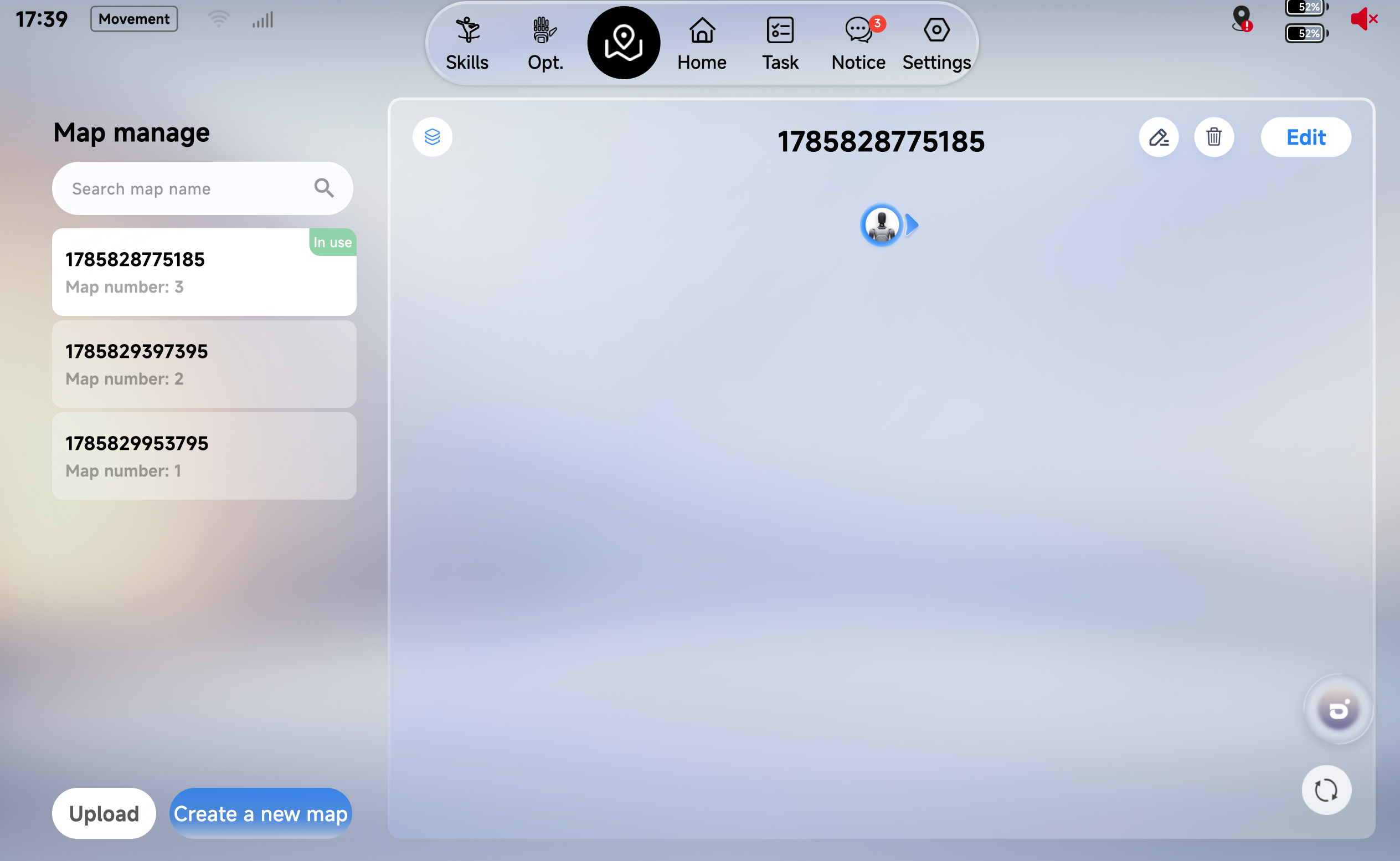
2. Tap Create Map and complete mapping of the exhibition area.
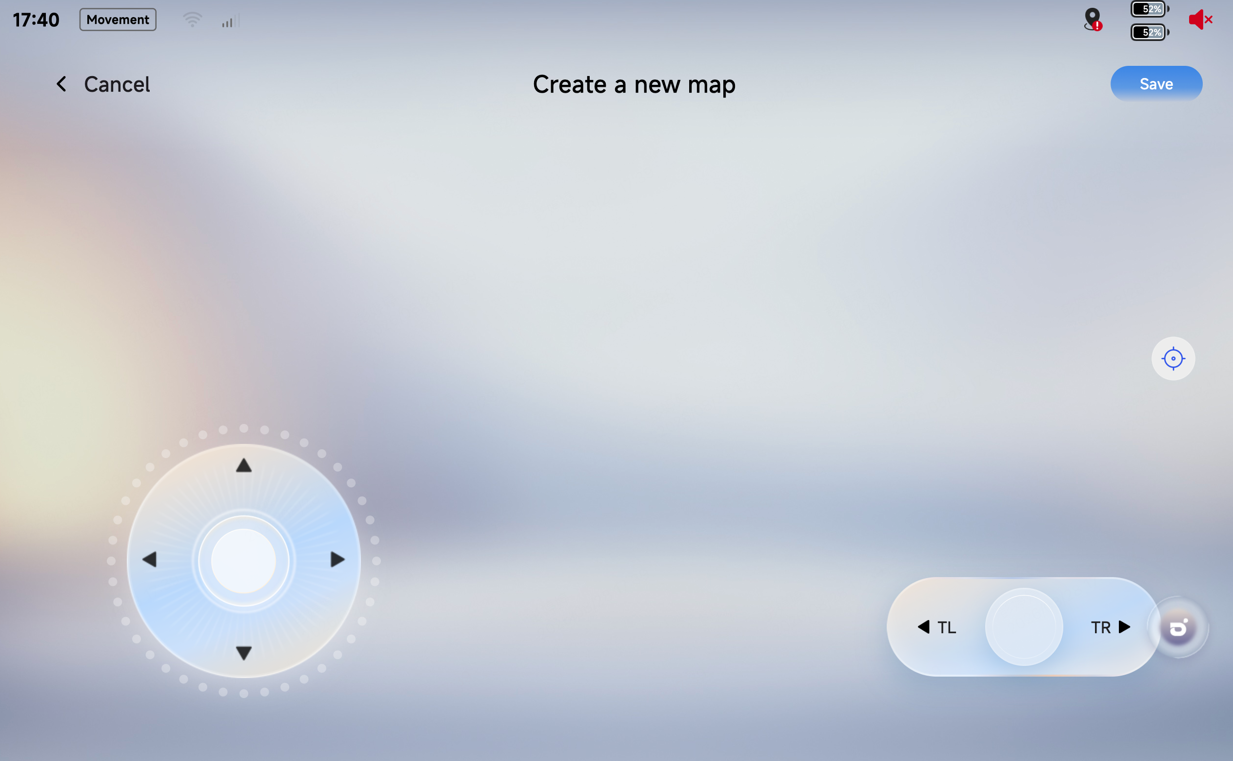
3. Enter Edit → Points and mark each explanation point on the map.
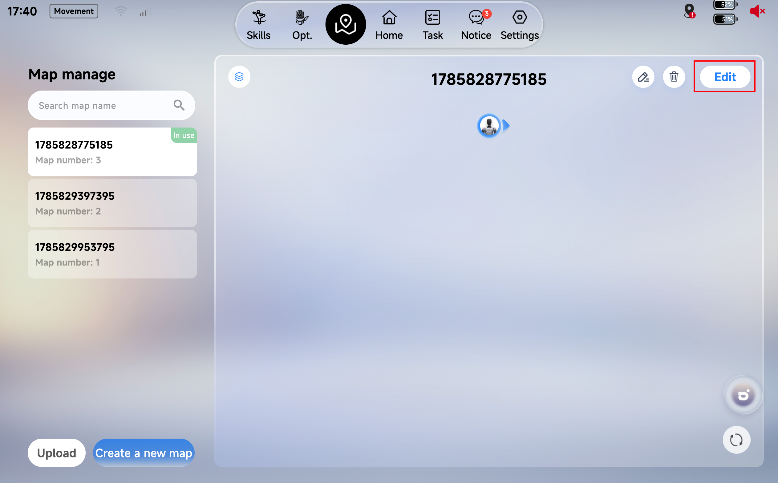
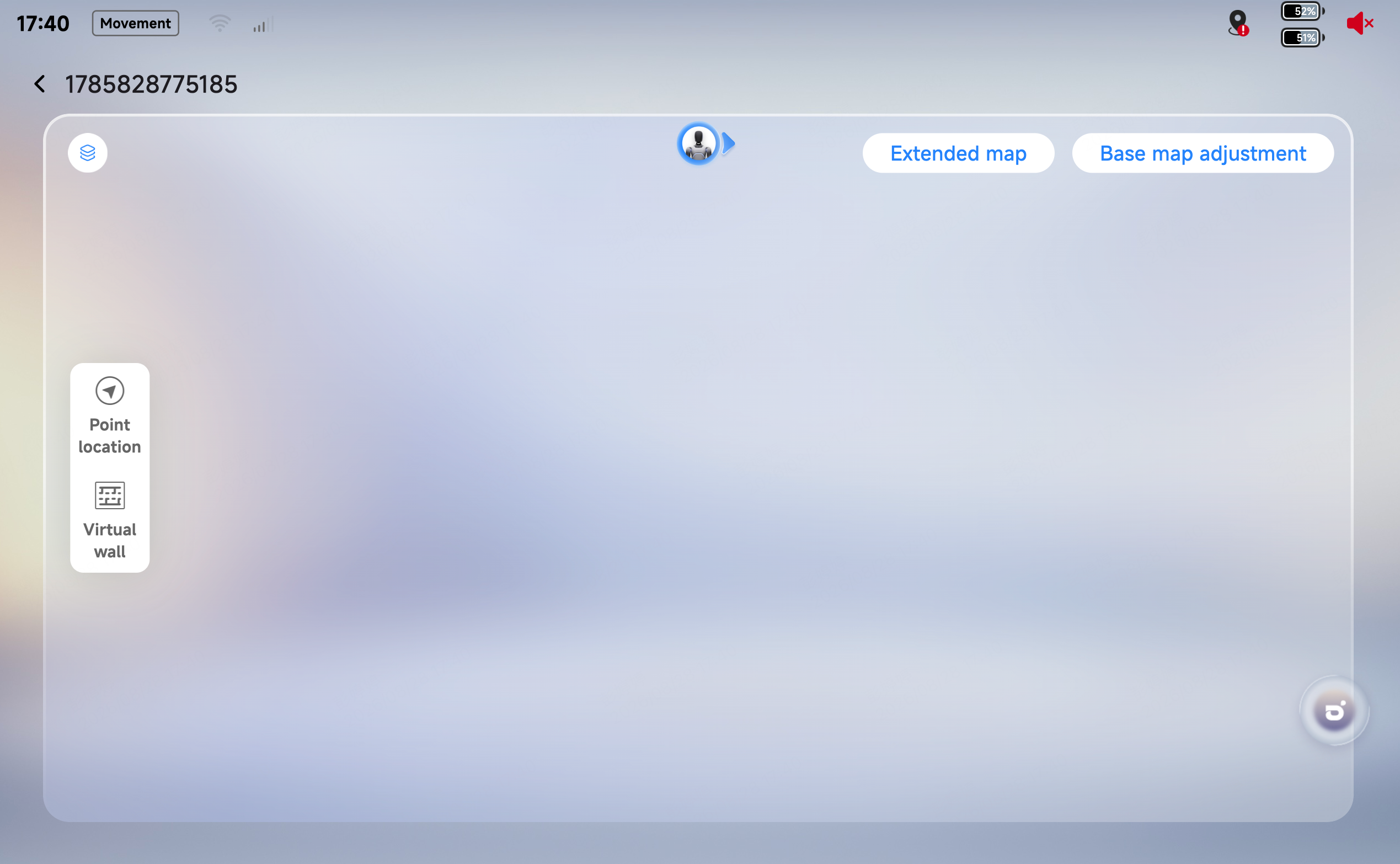
4. After editing, upload the map to the cloud.
5.6.2 LinkSoul Operations: Creating and Deploying a Task
Creating a task
1. Log in to the LinkSoul platform
Asia: https://linksoul-sg.agibot.com/
EU: https://linksoul-eu.agibot.com/
America: https://linksoul-us-east.agibot.com/
2. Enter the Resource Center.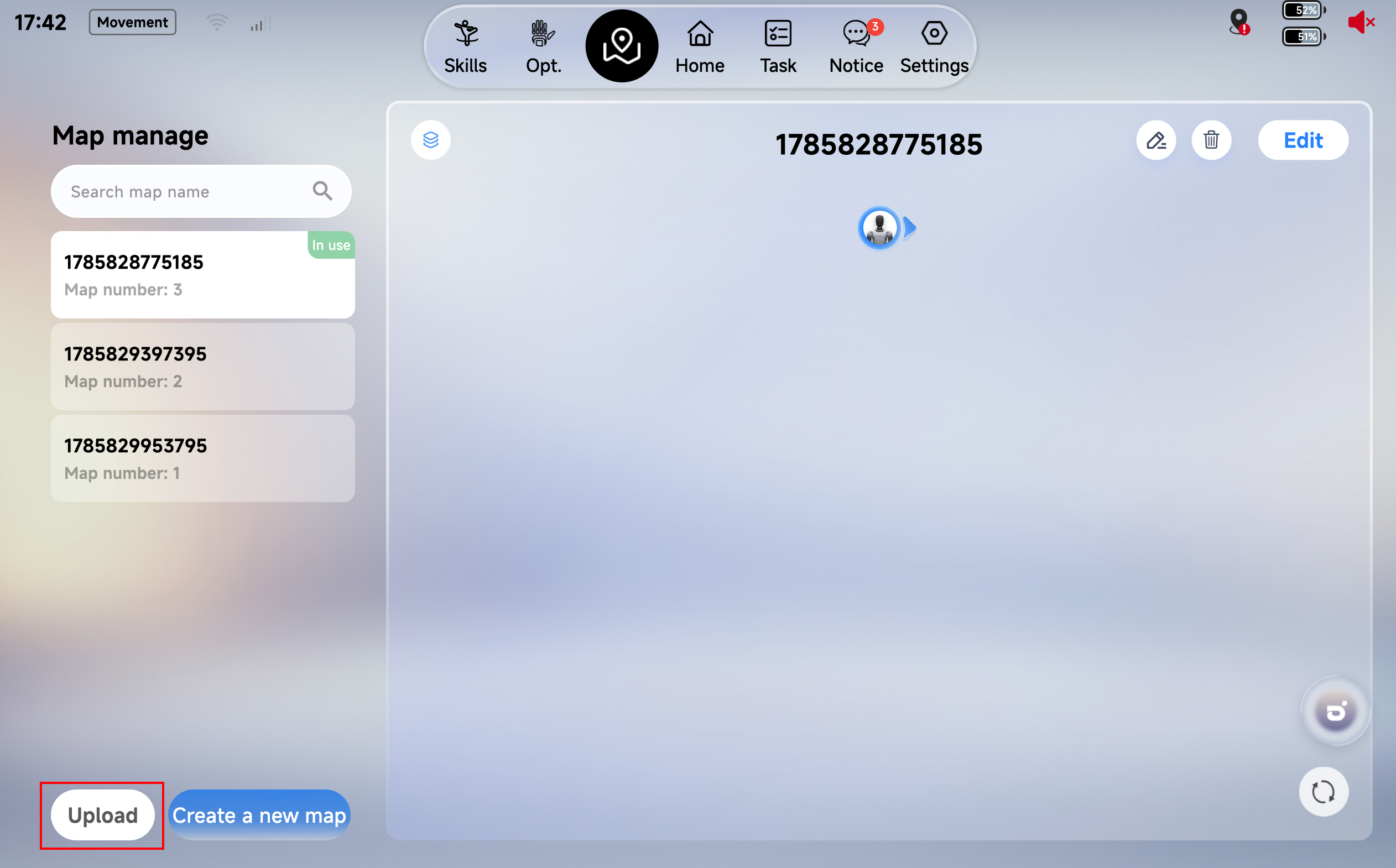
3. Tap Task Management.
4. Tap New Spatial Task and fill in the task name and other basic information.
5. Select the uploaded map from the map list.
6. Tap Confirm to finish creating the spatial task.
Editing a task
1. Tap the newly created task to enter the task editing page.
2. Add points: Select "Add Point" and add the points to be explained. When two or more points are added, you can set the robot to explain while walking between two points.
3. Trigger and run configuration: Set the execution mode to single execution or loop execution (loop execution supports an effective time window); trigger rules can be voice commands or perception commands (shoulder tap).
4. Point configuration: Set the expression, motion, and explanation content for each point; the truncation mode is customizable and defaults to "truncate at the end of the broadcast"; each point supports multiple explanation segments.
Configuring the agent
1. Tap Agent Center.
2. Tap Add Agent, select A3Ultra, and use the default template.
3. Tap the newly created agent to enter Resource Configuration.
4. Select Spatial Task, add the spatial task created earlier, and tap Save.
Binding and deployment
1. Tap Unbound Device at the bottom-right corner of the agent card, select the device and add it; the map and task will be deployed to the robot automatically.
5.6.3 Post-Deployment Verification
Task deployment confirmation. Open the client, enter the Task module, and confirm that the latest deployed spatial task is visible.
After receiving the task, trigger the spatial task in the following three ways to verify that the function works properly:
Trigger Method | Verification |
Client trigger | Trigger the spatial task manually in the client app and confirm the task starts normally |
Voice trigger | Trigger the spatial task with a voice command and confirm voice recognition and task startup work normally |
Shoulder-tap trigger | Trigger the spatial task by tapping the robot's shoulder and confirm motion recognition and task startup work normally |
Pass criteria: the robot can execute the exhibition explanation task normally along the preset route and points.
5.6.4 Client Trigger Method
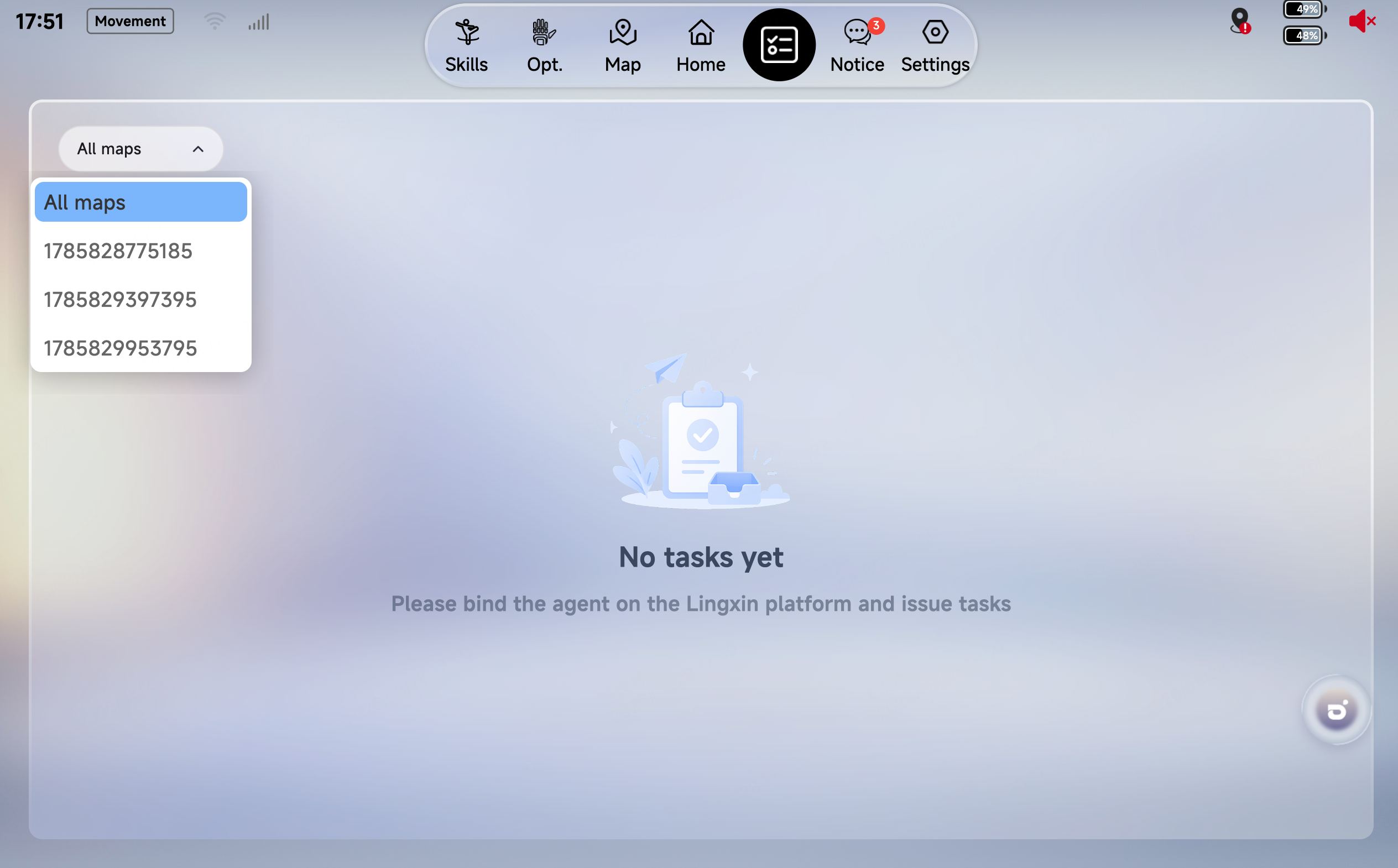
Tap the filter to show the required map. Tasks created in the LinkSoul platform will appear here after deployment. Then, tap [Start] under a task, and the robot will begin executing that task.
The LinkSoul Platform is a robot "Soul Workshop" launched by AGIBOT for both enterprise and individual users. Here, you can give a standard robot its own personality and soul. Through simple and intuitive operations, you can infuse the robot with emotion and thought, making it your dedicated intelligent companion.
• Individual Users: Can freely customize the robot’s interactive experience, including character design, personality, voice tone, knowledge base, skills, face and memory. Create your own "soul" on the platform and bind it to the device to bring the robot truly to life.
• Enterprise Users: Can use scenario-specific agent templates (e.g., exhibition guide, healthcare companion, smart shopping guide, front desk reception) to quickly integrate robots into business scenarios for efficient implementation and intelligent upgrading.
Detailed Usage Documentation for LinkSoul Platform:

Official website of LinkSoul Platform:
Asia: https://linksoul-sg.agibot.com/
EU: https://linksoul-eu.agibot.com/
America: https://linksoul-us-east.agibot.com/

5.8 LinkCraft Platform
LinkCraft is a robot content creation and performance platform launched by AGIBOT for general creators. The platform is dedicated to lowering the barrier to robot content creation, enabling users to easily create and publish robot performance content without any professional background in programming, control, or motion design.
Guided by the vision of "making creation simpler and expression more vivid", LinkCraft is designed around the following principles:
• Lowering barriers and expanding expression: Complex processes in traditional robot motion development (such as design, control, synchronization, and debugging) are abstracted and visualized, making content creation more intuitive.
• Multi-form hardware compatibility: LinkCraft is currently adapted to multiple AGIBOT robot models and will further extend to more types and forms of robot devices, building a cross-hardware shared system for motion choreography and unified expression.
• Fusion of AI and art: With AI motion recognition, voice-driven control, and multimodal synthesis algorithms at its core, the platform gives robots more natural and human-like expressiveness.
Official website:
China: linkcraft.agibot.com
America: linkcraft-us-east.agibot.com
Singapore: linkcraft-sg.agibot.com
5.9 Teleoperation
5.9.1 Functional Overview
The teleoperation function allows users to control the robot in real time through an operating terminal. After connecting to the robot, the user can perform operations such as movement, turning, and body motions with control devices such as controllers and VR equipment.
This function is applicable to scenarios such as remote control, manual takeover, debugging, and demonstration, helping users complete operations while keeping a certain distance from the robot.
5.9.2 Preparation
5.9.2.1 Site Requirements
• The ground should be flat, non-slip, hard, and level, free of potholes, cables, and other debris
• Reserve a safety distance of at least 1 m around the robot
• Reserve a safety distance of at least 1 m around the operator
5.9.2.2 Emergency Preparation
• The operator must know and be proficient in releasing the grip button (VR controller) to pause teleoperation • The operator must know and be proficient in pressing both the left and right sticks simultaneously (VR controllers) to trigger a damped emergency stop |
5.9.2.3 Equipment List
Category | Device | Qty | SW/HW | Level | Purpose | How to Obtain |
Robot | AGIBOT A3 | 1 | Hardware | Required | Teleoperated robot; can track the operator's movement | Purchase an official AGIBOT robot |
Official remote controller | 1 | Hardware | Required | Comes with the official AimMaster software; full-function control of the robot | ||
Teleoperation software | / | Software | Required | Functional software with teleoperation device connection and connection-method settings | ||
Teleoperation kit | VR headset (PICO 4 Ultra Enterprise) | 1 | Hardware | Required | Robot connection, head control, binocular video display, etc. | Purchase the official AGIBOT teleoperation kit |
VR controllers | 2 | Hardware | Required | Arm posture mapping, button operation, movement control, etc. | ||
Waist motion tracker | 1 | Hardware | Required | Waist posture mapping | ||
Leg motion trackers | 2/4 | Hardware | Required | Leg posture mapping | ||
GenieLink | / | Software | Required | Teleoperation control software installed on the VR headset; the software platform for controlling the robot via VR | ||
Network | Wireless router | 1 | Hardware | Required | Communication between the robot and VR devices | Purchase separately; parameter requirements are available from AGIBOT after-sales |
5.9.3 Network Deployment
• No video transmission mode
Complete the installation and power supply of the wireless router and connect it to the upstream switch; configure wireless parameters (SSID, band, channel, bandwidth, etc.) according to the site environment to establish a dedicated wireless network for robot teleoperation. Connect the robot and the VR devices to the same LAN.
5.9.4 Robot Deployment
5.9.4.1 Connecting the Robot to the Network
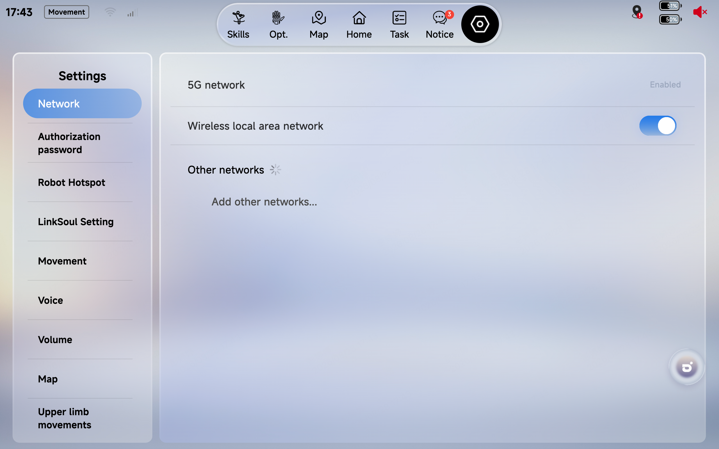
On the [Settings] → [Network] page of AimMaster, connect the robot to the deployed Wi-Fi network.
5.9.4.2 Enabling the [Teleoperation] Function
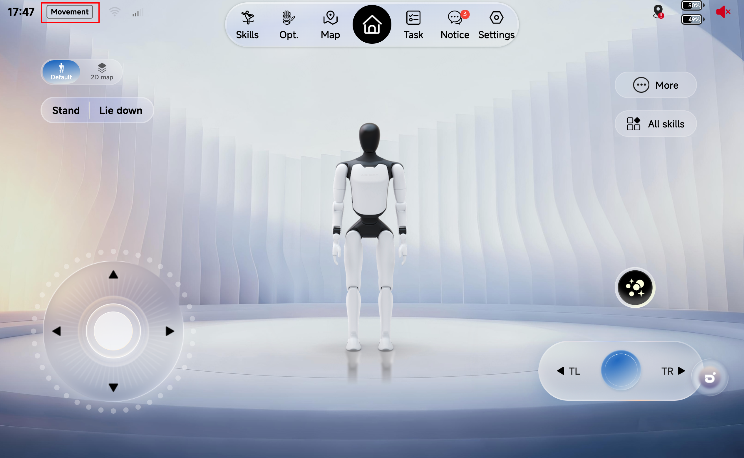
• On the AimMaster home page, confirm that the robot is in the motion state.
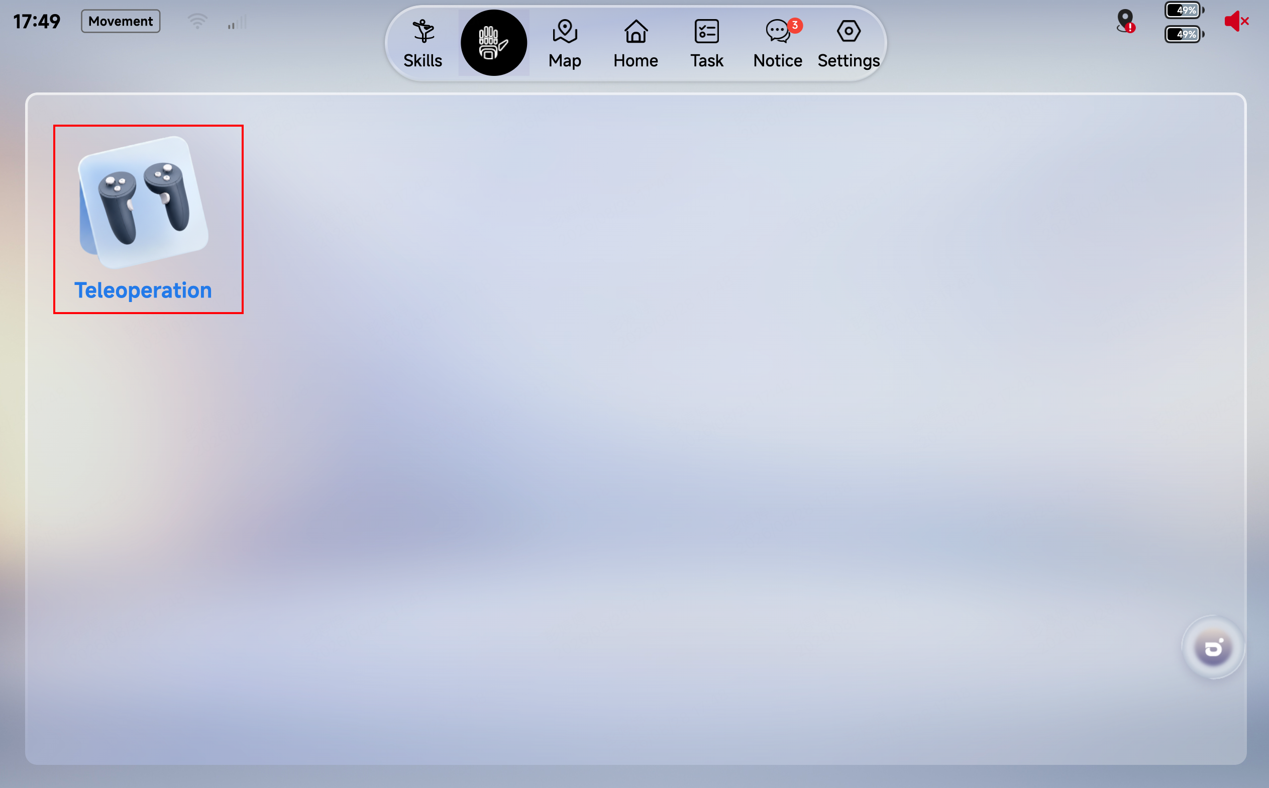
• On the [Operation] page of AimMaster, enter the [Teleoperation] function.
5.9.4.3 Configuring the Connection Method
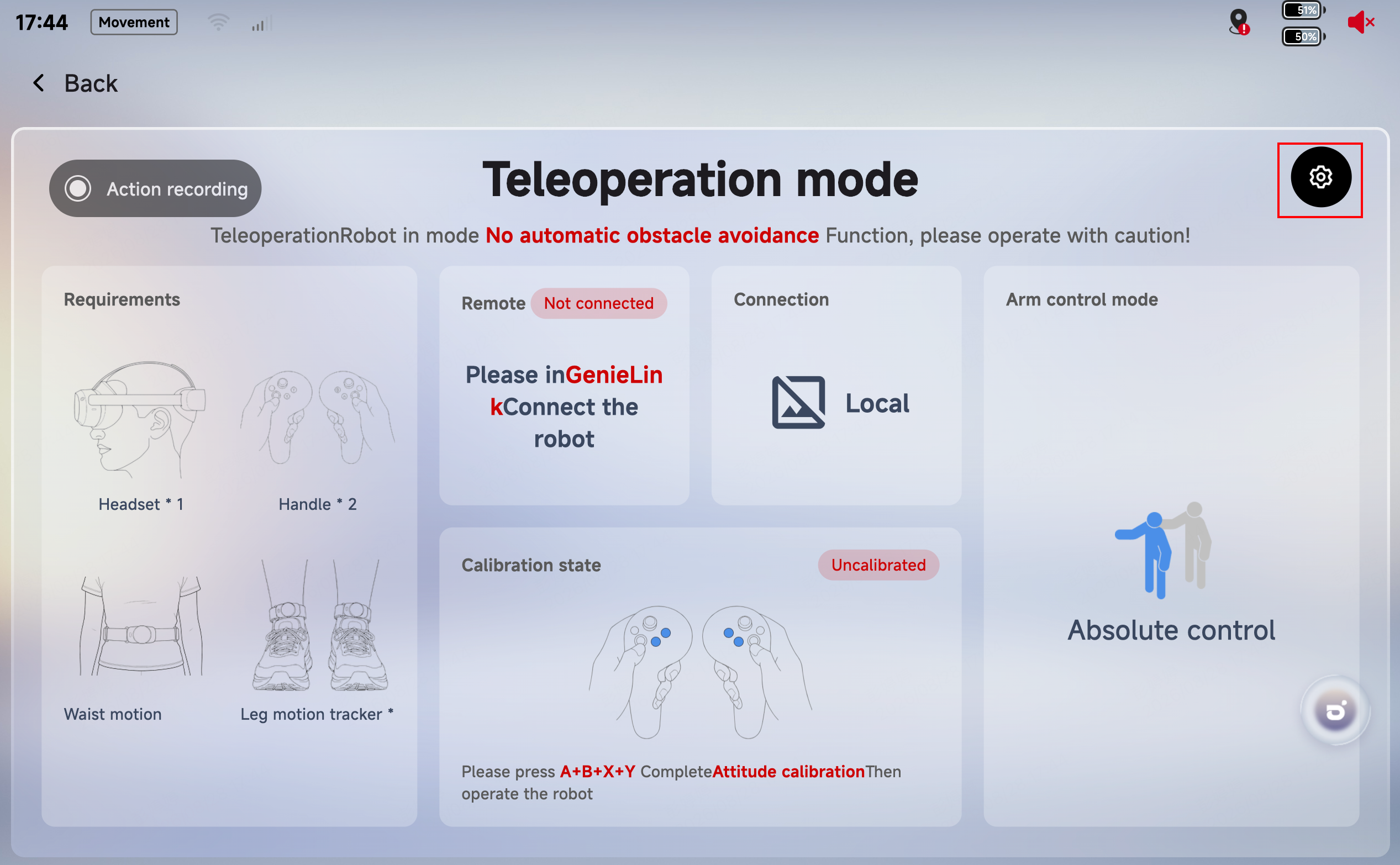
1. Step 1: On the [Teleoperation] page, tap Settings to enter the [Settings] page.
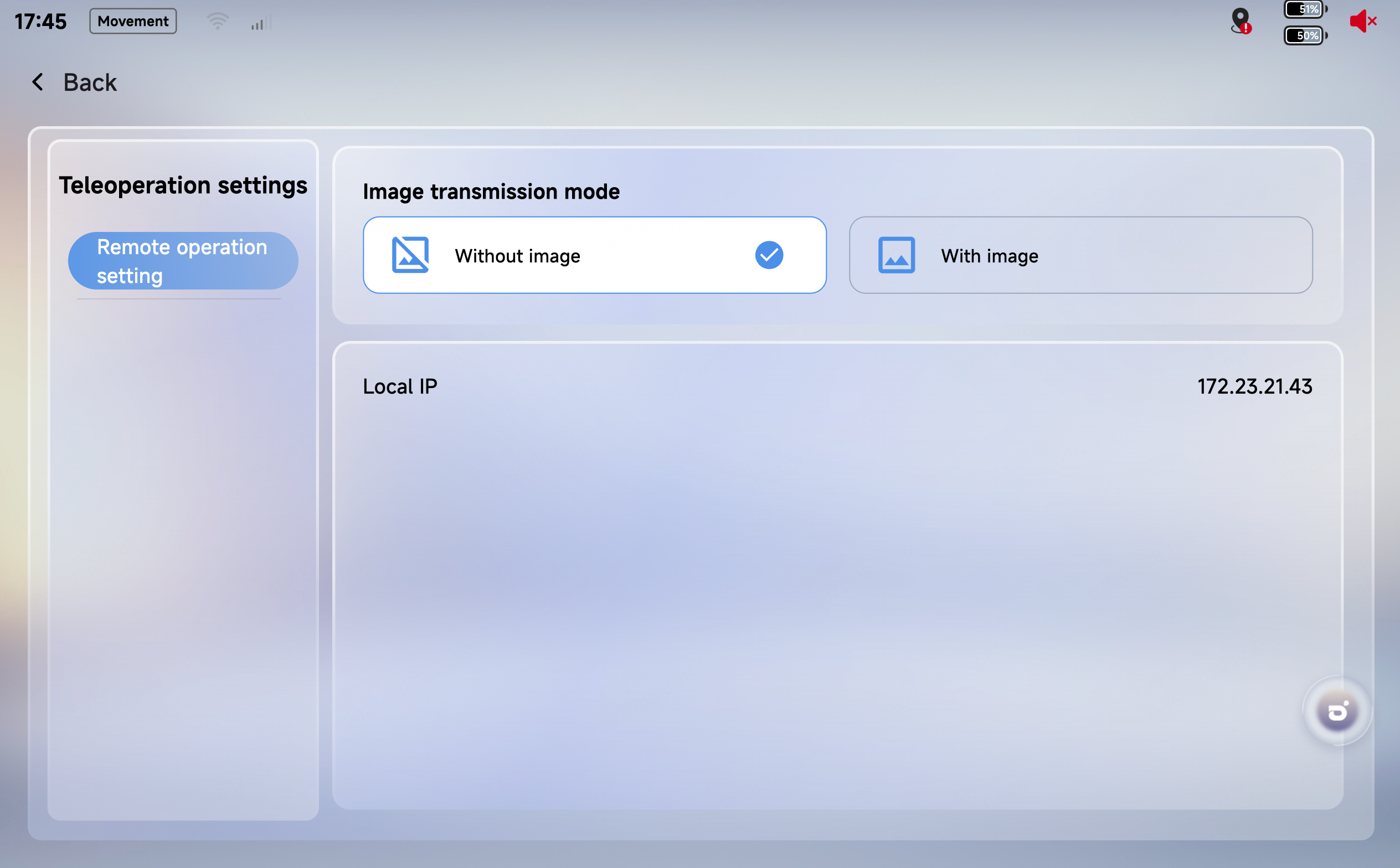
2. Step 2: On the [Settings] → [Teleoperation Settings] page, select the no-video-transmission mode (default; the video-transmission mode is not yet available). The no-video-transmission mode has only one connection method, so no selection is needed, and no connection credentials need to be entered manually.
5.9.5 VR Device Deployment
PICO basics: • Move the controller to move the cursor • The trigger button on the controller is the confirm button • Press and hold the Home button on the VR controller to move the view window to the position the controller points to |
5.9.5.1 Device Description
VR devices (3-tracker solution) | |
| |
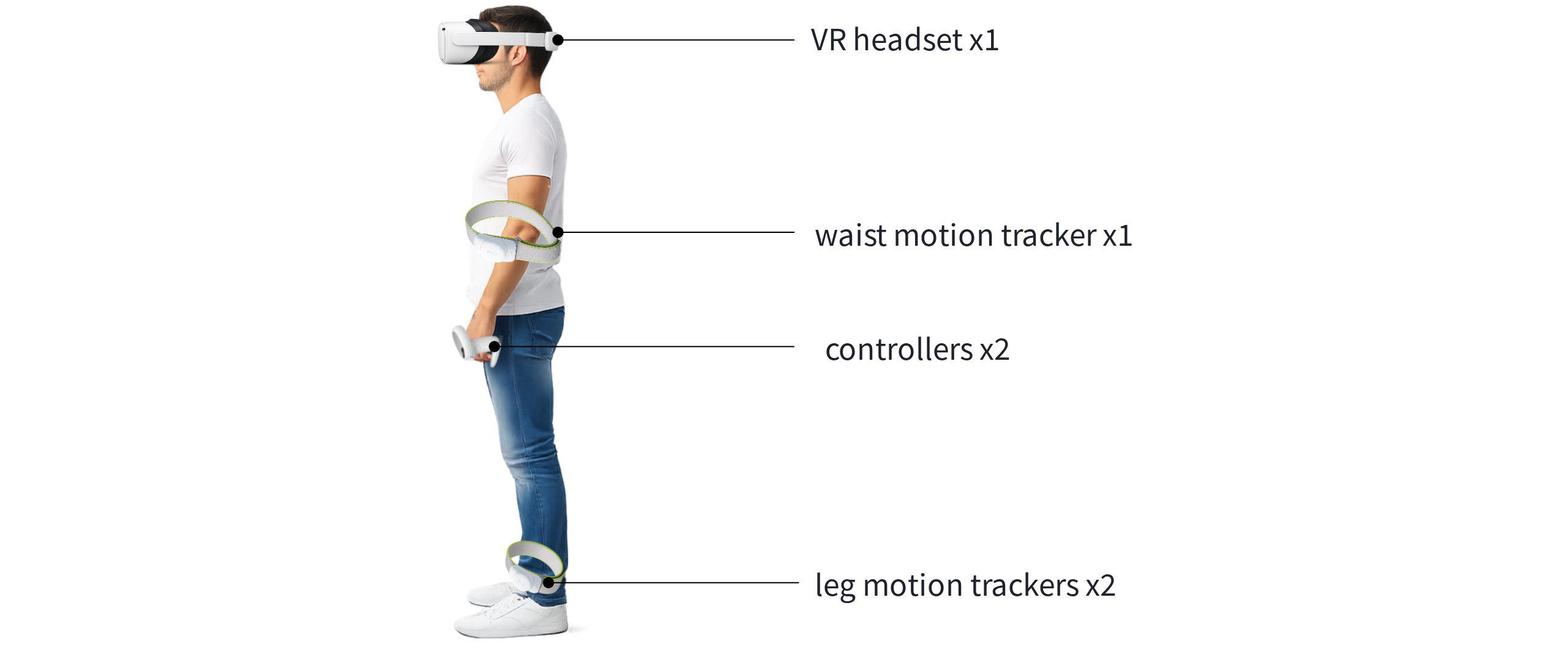
Equipment list | VR headset x1, controllers x2, waist motion tracker x1, leg motion trackers x2 |
Video display | VR headset |
Head control | VR headset |
Arm control | VR controllers |
Waist control | Motion tracker |
Leg/foot control | Motion trackers |
Hand control | Specific gestures: VR controllers |
Remote-controlled movement | VR controller sticks |
5.9.5.2 Device Connection and Wearing
Note: • Make sure the motion trackers are strapped tightly to the body to prevent shifting or falling off during movement (severe shifting or falling off may cause the robot to fall) • Make sure the VR headset is worn correctly on the head • Make sure the operator's clothing or other objects do not block the trackers; otherwise tracking performance will be affected • After putting on the motion trackers, make sure the tracker indicator lights point vertically upward when standing upright • Calibration may not be possible in direct sunlight; calibrate indoors or in the shade |
Procedure:
1. Connecting the controllers to the VR headset: To connect new controllers, go to [Settings] → [Controllers] on the headset and tap [Pair]; press and hold the Home button and trigger button on the controller until the status indicator flashes alternately red and blue, then release and follow the on-screen instructions.
2. Wearing the VR headset: 1) Lift the rear head pad, put the headset close to your eyes, and adjust it so the view is unobstructed and the image is clear; 2) Once it fits comfortably, fasten the rear head pad and tighten the knob at the back of the head; 3) Fine-tune the top strap so it bears some load to reduce pressure on the forehead.
3. Wearing, pairing, and calibrating the motion trackers: 1) Press the tracker power button for 2 s to turn it on; 2) Wear it on the corresponding positions (ankles, waist, etc.); 3) Open the "Motion Tracker" app in the VR headset and tap [Start Pairing] to complete pairing; 4) Tap [Start Calibration], select the wearing mode, and follow the instructions to complete calibration.
Reference Documents:
Motion tracker calibration checklist: • Confirm that the avatar's posture is normal • Confirm that the avatar's feet are properly in contact with the ground • When standing upright, confirm that the avatar is also basically upright • Confirm that the body shows no obvious tilting, drifting, sinking, or floating |
5.9.5.3 Setting the Safety Boundary
After turning off the "Permanent safety protection switch", the operator's range of movement is no longer restricted, but the operator must pay attention to environmental safety while moving. |
On the [Settings] → [Developer Options] page, turn off the "Permanent safety protection switch".
5.9.5.4 Connecting the Device to the Network
Connect to a stable network under [Settings] → [Wi-Fi].
5.9.5.5 Connecting to the Robot
1. Step 1: Open the installed GenieLink app from the VR headset's app list.
2. Step 2: On the settings page, select the connection method and enter the corresponding credentials; select "No video transmission" → "Wireless connection".
3. Step 3: Follow the connection method configured in AimMaster to connect to the target robot.
4. Step 4: Tap "Confirm" on the "Safety boundary disabled" pop-up.
5. Step 5: Once connected, "Connected" is displayed and the app switches to the operation page.
5.9.6 Operation Guide
Note: • Before operating the robot, make sure the motion trackers have been calibrated • Before operating the robot, make sure posture calibration has been completed • Before operating the robot, make sure the complete human skeleton attached to the operator is visible in the VR headset • During teleoperation, do not move or remove the VR headset or motion trackers • After pausing teleoperation, the VR headset can be removed temporarily, but after putting it back on, the motion trackers must be recalibrated and posture calibration must be performed again |
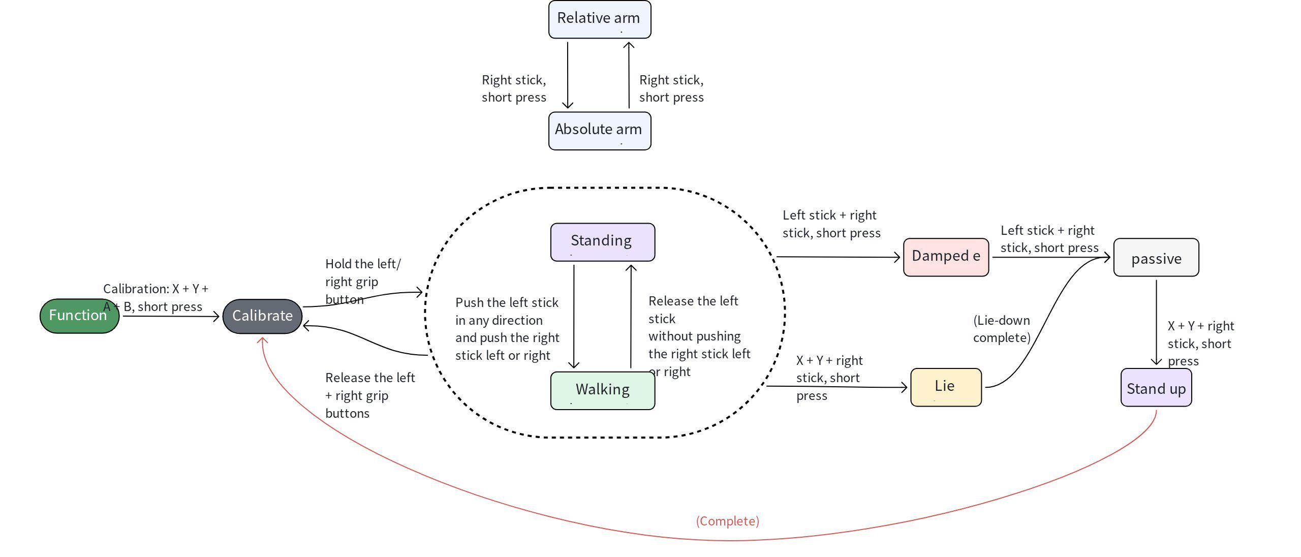
5.9.6.1 Overall Workflow
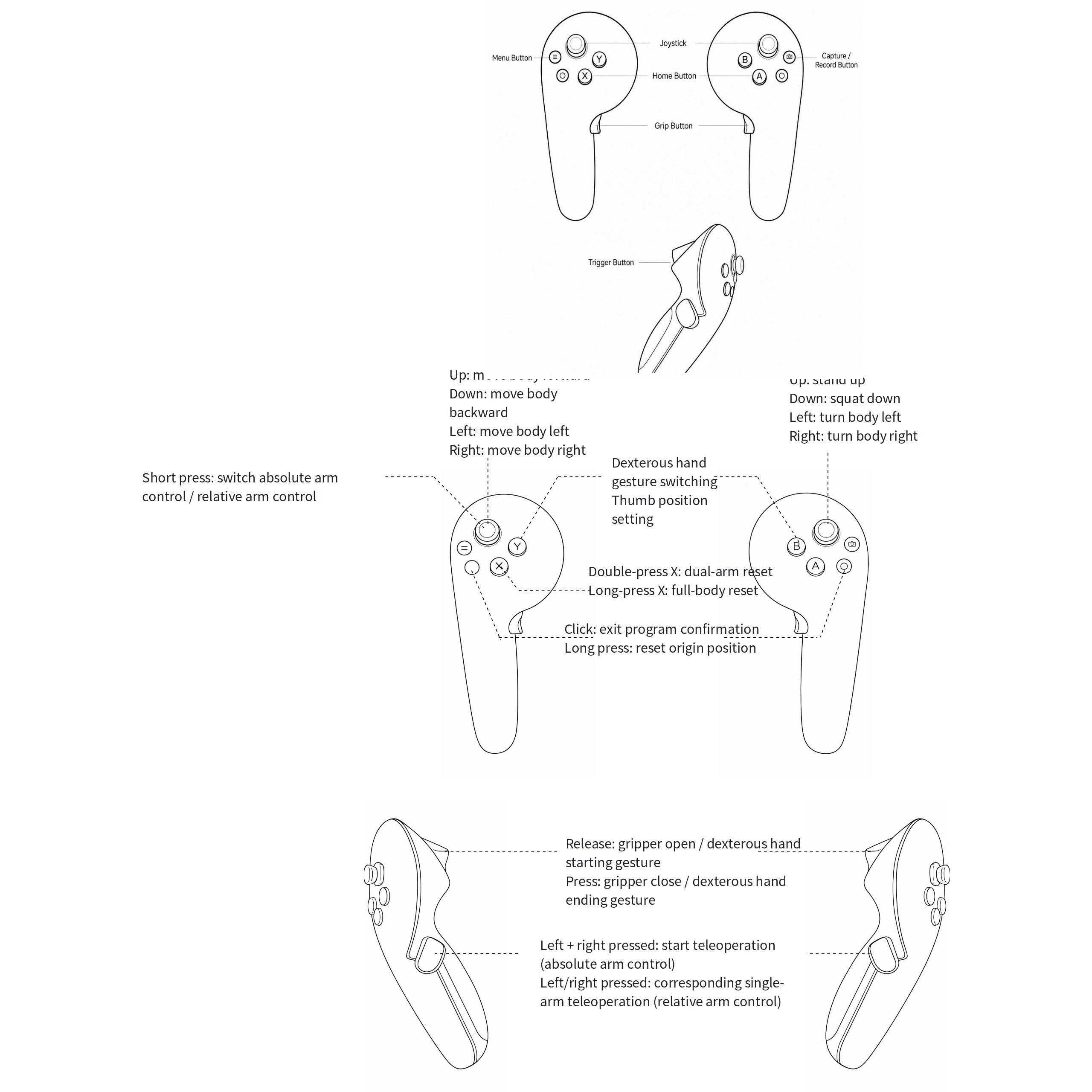
5.9.6.2 Global VR Controller Button Mapping
Operation | Buttons | Description |
Posture calibration | X + Y + A + B (pressed simultaneously) | The operator must stand upright, face forward, and let both hands hang naturally |
Start / pause teleoperation | Press / release the grip button | When teleoperation starts, the robot's upper body follows the operator's posture; when paused, the robot's upper body holds a stable fixed posture • Absolute arm control: press left + right grip buttons simultaneously to start; release either grip button to pause • Relative arm control: the left/right grip button independently controls the left/right arm |
Switch absolute / relative arm mode | Short press the left stick | • Absolute arm mode: the robot's arms follow the operator's arm position and posture in real time for intuitive, synchronized motion mapping • Relative arm mode: based on the robot's current arm posture, the robot's arms move incrementally according to the operator's relative motion — suitable for fine adjustment and continuous operation |
Dual-arm reset | Double-press X | Resets both robot arms to the initial state |
Full-body reset | Long-press X | Resets the whole robot to the initial state |
Damped emergency stop | Short-press left stick + right stick | In any mode, puts the robot into the damped emergency-stop state |
Switch from damped to passive | Short-press left stick + right stick | After a damped emergency stop, switches the robot to the passive state with all limbs disabled |
Lie down | Short-press X + Y + right stick | In normal walking mode, it makes the robot lie down |
Stand up | Short-press X + Y + right stick | When the robot is lying down / in passive state, makes the robot stand up again and enter normal walking mode |
5.9.6.3 Posture Calibration
Note: Posture calibration is a mandatory step before starting operation. It establishes the posture correspondence between the operator and the robot; otherwise motion mapping will be inaccurate, and in severe cases the robot may fall. |
• Step 1: The operator stands upright, faces forward, and lets both hands hang naturally at the sides of the body
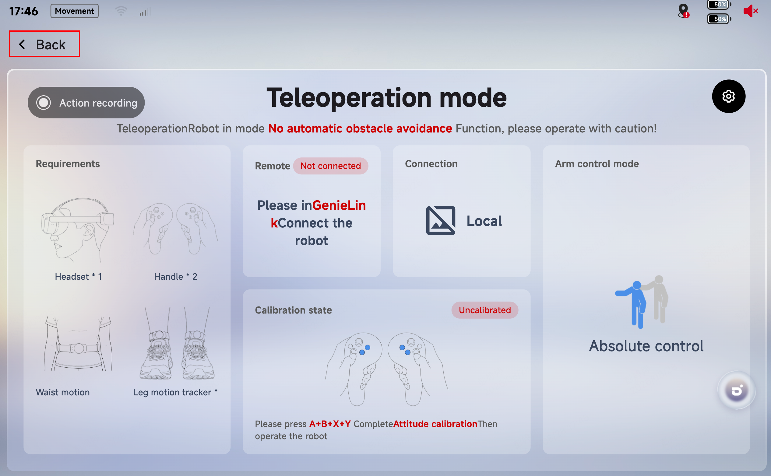
• Step 2: Press X + Y + A + B on the VR controllers simultaneously; a pop-up in the VR headset indicates "Calibration started"
• Step 3: Calibration succeeds when the VR headset shows "Calibration complete" and the [Calibration Status] field in AimMaster shows "Calibrated"
5.9.6.4 Pausing / Resuming Teleoperation
Note: After pausing teleoperation, the left and right sticks can still control leg movements — be careful not to touch the controller accidentally. |
• Pause:
○ Absolute arm control: release either grip button
○ Relative arm control: release both the left and right grip buttons
• Resume:
○ Absolute arm control: press the left + right grip buttons simultaneously
○ Relative arm control: press the left/right grip button
• Operating restrictions while paused: When buttons or sticks are operated in the paused state, a VR pop-up indicates "Teleoperation is paused; the robot cannot be controlled"
• Catch-up after resuming: After resuming teleoperation, the robot smoothly converges to the current operating posture (absolute arm control)
5.9.6.5 Arm Control Modes
A short press of the left stick switches between absolute arm control and relative arm control; a pop-up in the VR headset confirms the switch.
Mode | Switch Method | Description | Note |
Absolute arm mode | Short-press the left stick | The robot's arms follow the operator's arm position and posture in real time for intuitive, synchronized motion mapping | Default |
Relative arm mode | Short-press the left stick | Based on the robot's current arm posture, the robot's arms move incrementally according to the operator's relative motion — suitable for fine adjustment and continuous operation |
5.9.6.6 Teleoperation Modes
• Teleoperation mode
Mode | Switch Method | Description |
Standing teleoperation mode | Release the left stick; do not push the right stick left or right | The robot keeps a standing posture while the upper body follows the operator's motions; the right stick controls squatting / standing up |
Walking teleoperation mode | Push the left stick in any direction; push the right stick left or right | The sticks control the robot's movement, turning, squatting / standing up, while the upper body follows the operator's motions |
• Lower-limb movement controls
Action | Operation |
Move forward / backward | Push the left stick forward / pull it back |
Move left / right | Push the left stick left / right |
Turn left / right | Push the right stick left / right |
Stand up / squat down | Push the right stick forward / pull it back |
• End-effector controls
Category | Action | Operation | Description |
Gripper | Grip | Press the trigger button | |
Open | Release the trigger button | ||
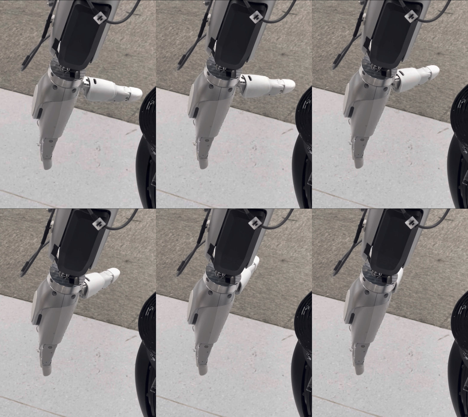
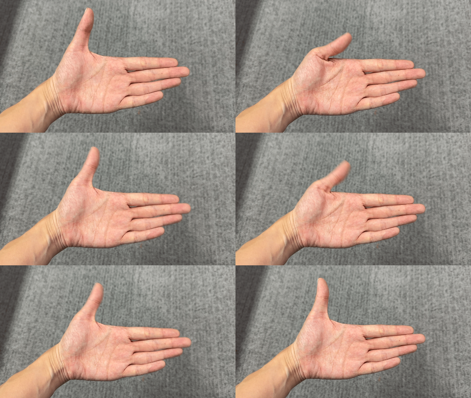
Dexterous hand
| Initial gesture | Release the trigger button | |
Final gesture | Press the trigger button | ||
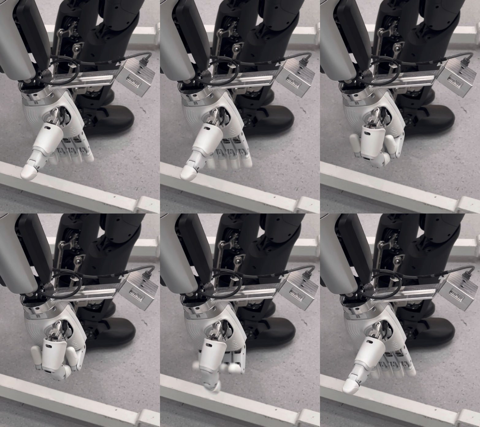
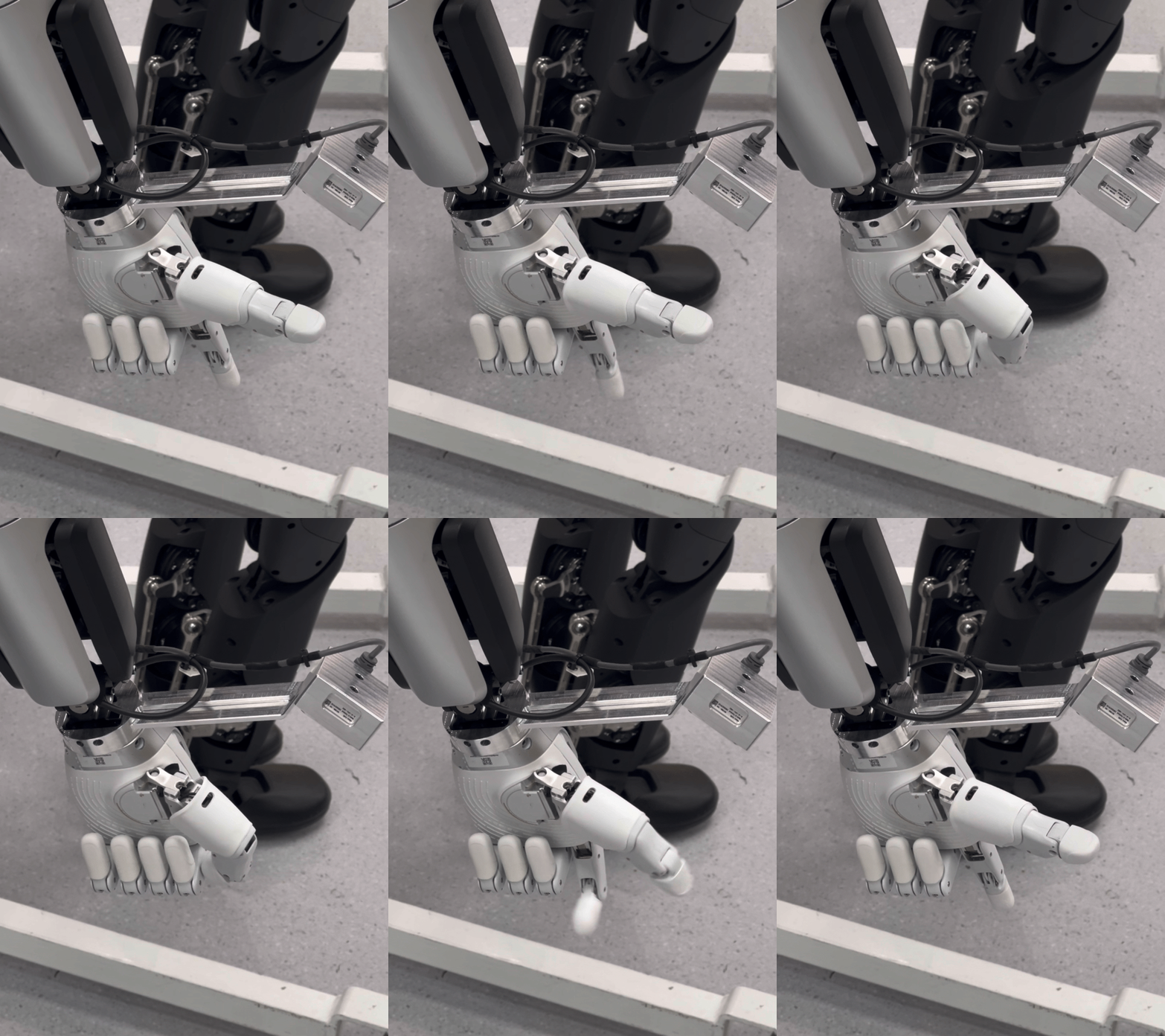
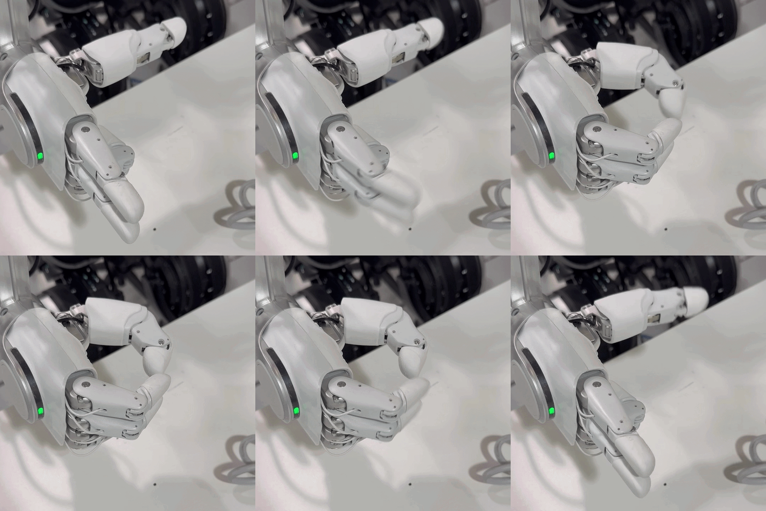
Switch left-hand gesture
| Y button + left trigger button | Cycles through the three gesture types below: • "Five-finger closed grip"
• "Three-finger tucked grip" • "Three-finger straight pinch"
| |
Switch right-hand gesture | B button + right trigger button | ||
Switch left/right-hand thumb DOF 1 | Long-press Y / B |
| |
Switch left/right-hand thumb DOF 2 | Short-press Y / B |
|
5.9.6.7 Reset
While teleoperation is paused, the robot can be reset in the following ways:
Reset Method | Operation | Description |
Dual-arm reset | Double-press X | Resets both robot arms to the initial state |
Full-body reset | Long-press X | Resets the whole robot to the initial state |
Stop reset | Double-press X | If an unexpected situation occurs during reset, the reset motion can be stopped manually |
5.9.6.8 Emergency Stop
The operator must know and be proficient in pressing the left/right sticks simultaneously (VR controllers) to trigger a damped emergency stop. |
• In an emergency, press the left and right sticks simultaneously to trigger a damped emergency stop; the robot immediately enters a safe damped state
• After a damped emergency stop, pressing the left and right sticks simultaneously again switches the robot to the passive state, in which the robot's posture can be adjusted freely
5.9.6.9 Lie Down
Press X + Y + right stick simultaneously to make the robot lie down. After lying down is complete, the robot automatically switches to the passive state.
5.9.6.10 Stand Up
In the passive state, press X + Y + right stick simultaneously to make the robot stand up again. After standing up is complete, teleoperation can continue.
5.9.7 Exiting the Function
1. Step 1: Pause teleoperation and confirm that the robot is standing stably
2. Step 2: Single-press the Home button on the controller, and tap Exit on the exit confirmation pop-up
3. Step 3: Tap Back on the function home page of AimMaster to exit
5.9.8 Exception Alarms
Abnormal State | VR On-Screen Message | System Response | Recommended Operator Action |
A severe fault that may cause the robot to fall | "The robot is at risk of falling; operation interrupted" | Interrupt the function | Exit teleoperation immediately, lift the robot up, and check the robot's condition |
A fault affecting robot operation | "Robot abnormal; operation interrupted" | Interrupt the function | Exit teleoperation immediately and check the robot's condition |
A fault whose operating conditions will gradually worsen | "The robot is at risk; please check after use" | - | May continue, but keep monitoring whether the robot's condition worsens |
Network latency of 200–1000 ms | "High network latency; operation slowed down" | Robot motions slowed down | Pausing teleoperation and checking the network is recommended |
Network latency greater than 1000 ms | "High network latency; operation interrupted" | Interrupt the function | Exit teleoperation immediately and check the network |
5.10 Data Collection
Data collection refers to recording the robot's motion data and sensor data during operation through teleoperation and other means. Once sufficient high-quality real-robot data has been collected, it can be used to train the robot's AI models, enabling the robot to perform tasks autonomously.
Detailed documentation:
AGIBOT A3 Ultra Data Collection User Manual V3.2
5.11 Fleet Control
5.11.1 How to Obtain
Please contact after-sales personnel to obtain the "Fleet Control software package".
5.11.2 Project Management
Each project is a separate engineering file. After creation, it can be shared among multiple people through export and import.
• Create New Project: Tap the Create New Project button to create a new project.
• Export: Tap the Export button in the top-right corner, select the file to export and name it, to generate a .gcs file.
• Import: Tap [Import Existing Project] and select a .gcs file to quickly open an exported project.
• View Project History: Displays previously edited projects; tap to open a project.
• Delete Project History.
Note: Due to the refactoring of the software interface, projects from historical versions (before v1.2) can no longer be opened.
5.11.3 Robot Management
• Add Robot: Tap the [Add Robot] button and fill in the relevant information according to the input box prompts. Multiple robots can be added at once, in the format: "A3 @ Robot Nickname @ IP".
Robot status:
1. Robot nickname (the name given when adding the robot)
2. The robot’s current Action
3. The task the robot is currently executing (this task is a multi-robot control task)
4. Robot status (latency with the current computer, manual/automatic state, emergency stop state, Wi-Fi signal, battery information, etc.)
5. The correction effect after time synchronization
6. The reconnect button, etc.
• Function Buttons: The checkbox at the front of the card has two states, selected or unselected; this box affects the scope of functions such as deletion, time synchronization, and resource synchronization. To quickly select only one robot and set all other robots to unselected, double-click that robot’s card.
• Time Synchronization: Using this function calculates the time difference interval of the selected robots and caches this data.
Note: When you need to control multiple robots for synchronized operation, be sure to tap Time Synchronization in advance; it can be performed multiple times.
5.11.4 Menu Bar
Tap the top-left corner to show the menu bar.
• "Skip Startup Status": Only supported on A2.
• "Execute After": Sets the preparation time before a task is executed (when the network condition is poor, a longer preparation time can be set to ensure that the robots execute commands simultaneously).
• "Close Project": Ends the current project and returns to the home page.
5.11.5 Audio
Tap [Import Audio].
• Local Audio: Select and upload a file. The program will automatically convert it to a format supported by the robot. The name of the selected audio file is filled in by default during import and can be changed; when files have duplicate names, the new resource will overwrite the existing audio resource.
• Text-to-Speech (TTS): Enter text and call the TTS service (ensure network connectivity) to generate audio; the audio must be named manually.
• Tap [Sync Audio Resources to Robots] to sync all audio resources to the robots, with the robot scope being the robots selected previously.
Note: Synchronization is required each time after adding audio resources.
5.11.6 Automatic Tasks
❗ Before starting control with Multi-Robot Control, ensure the robots are idle (not walking, performing actions, dancing, etc.).
If abnormal operation occurs, restart the software; data will not be lost.
5.11.6.1 Roles
• Roles can be created using the [Add Role] button on the left side of the timeline. Each role generates one task track.
Role card functions:
1. Tap the [Selection Box] to adjust which robots are bound to this role, within the scope of the preceding robot list.
2. Press and hold the card to drag it and adjust the order of the roles up and down.
3. Tap the [Delete] icon to delete a role and all its associated content, without affecting the robot itself.
4. Tap the [Copy] icon to copy this role’s tasks to other roles.
5. Tap the [Hide] icon (a special state) to temporarily hide a role; when a task is issued, this role will not participate in execution.
5.11.6.2 Task Orchestration
Each role has its own timeline, and each role can run five types of task commands simultaneously:
1. Audio: Audio created in audio management; its duration is fixed to the audio length. Audio tasks can overlap, and the later overlapping audio task interrupts the playback of the previous one, but two audio tasks cannot be created to start at the same time.
2. Expression: A task from the robot’s expression list; the expression plays in a loop until the next expression task starts.
3. Action: A task from the robot’s action/dance list; the action duration is the action’s fixed length. Tasks can overlap, and the later overlapping action task interrupts the playback of the previous one, but two action tasks cannot be created to start at the same time.
4. Movement: Properties such as walking speed, turning, and time of the task can be set.
5. Status: Currently supports Action switching, volume setting, and microphone on/off.
5.11.6.3 Create / Edit Tasks
• Right-click a task to show the Edit, Copy, and Delete buttons:
• Edit: Tap to bring up the edit dialog to modify task information.
• Copy: Copies the task information.
• Delete: Deletes the task (after selecting the command, pressing the keyboard Delete key also deletes it).
• Right-click a blank area to show the Create and Paste buttons:
• Create: Tap to bring up the create dialog to quickly create task information.
• Paste: Tap to quickly create a task by pasting the copied task.
5.11.6.4 Execute / Cancel Tasks
• Tap [Execute Task] in the top-right corner and confirm.
• The task delivery progress and execution countdown are shown; to cancel a task, tap the [End] button in the top-right corner before the execution countdown ends.
• Stage Preview.
6. Accessories Management and Usage
6.1 4G/5G Module User Guide
Robots are equipped with built-in eSIM cards. For details on the specific configuration and warranty services, please refer to Section 8.1 of this document.
6.1.1 eSIM Usage Instructions
• Communication standard: Supports 5G/4G.
• Plan: 100 GB of data per month. Once the data is used up, mobile network service stops; to continue using it, contact AGIBOT after-sales to purchase a data add-on package.
• Free period: Up to 1 year. To continue using it after expiry, contact AGIBOT after-sales to renew.
• Activation: Automatically activated after the device powers on.
• Network usage: The eSIM is enabled by default. When the device connects to Wi-Fi, the Wi-Fi network is used preferentially; when Wi-Fi disconnects, the mobile network is used automatically.
6.1.2 SIM Card Specifications
The A3 Ultra supports Micro-SIM cards for internet access. Its cellular communication module is compatible with 4G/5G protocols, and supports carriers including China Mobile, China Unicom, and China Telecom.
6.1.3 SIM Card Purchase
Because some functions of the A3 Ultra require access to AGIBOT’s servers, whitelist configuration is required, and a dedicated enterprise IoT card must be purchased from an AGIBOT partner. The advantage of an enterprise IoT card is that no personal real-name verification is required—only the business license and the front and back of the legal representative’s ID are needed. In addition, it supports a unified card management platform that can monitor in real time the card’s order and delivery status, data usage, balance and renewal, etc.
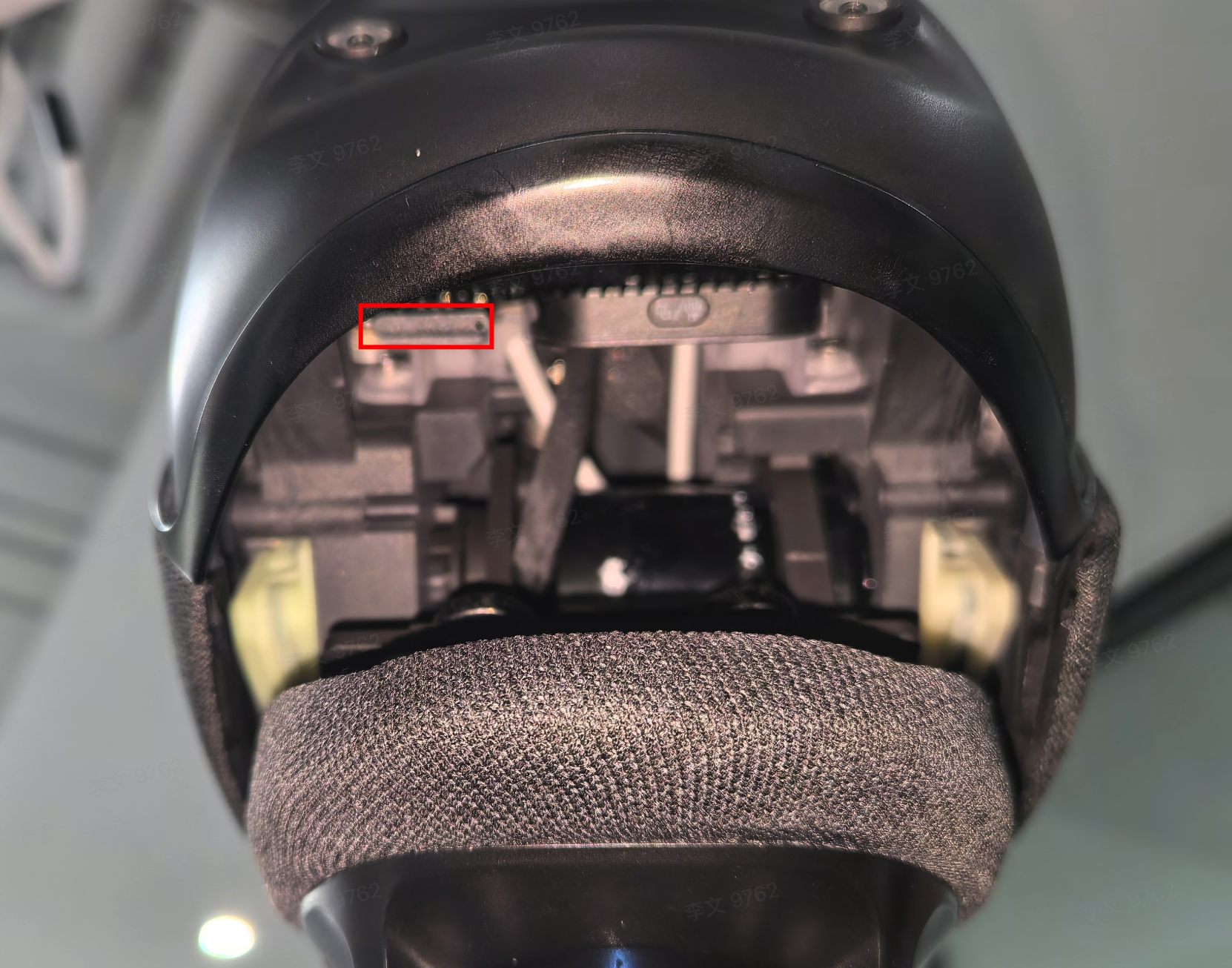
6.1.4 SIM Card Insertion
Flip the head upward and insert the SIM card into the corresponding slot from the neck of the robot.
7. Daily Maintenance and Management
1. Safety Warnings
• a. Power-off Maintenance: Before any maintenance or component replacement, completely power off the device and confirm it is in a fully de-energized safe state.
• b. No Unauthorized Modification: Do not modify the robot or alter its original design and configuration without authorization.
• c. Professional Repair Only: Do not disassemble the robot personally. If maintenance is required, contact the manufacturer’s designated professional service personnel.
2. Maintenance and Upkeep
• a. Routine Maintenance: Perform regular maintenance in accordance with the manufacturer’s (AGIBOT) recommendations to keep the robot in optimal operating condition.
• b. Use Original Spare Parts: Only use manufacturer-specified original spare parts for component replacement to guarantee equipment performance and operational safety.
3. Fault Handling
• a. Fault Response: Immediately stop operation once any malfunction occurs during operation, and notify professional technicians to conduct inspection and repair.
• b. No Unauthorized Disassembly & Repair: Do not disassemble or attempt to repair the robot by yourself, so as to prevent further damage.
4. Battery and Power Management
• a. Safe Charging: Do not disassemble the battery for separate charging; charge only by connecting the power supply.
• b. Charging Environment: The robot’s battery shall be charged in a safe, dry environment. Avoid humid and high-temperature surroundings.
• c. Prevent Overcharging: Do not keep the device connected to power for a prolonged period to avoid battery overcharging and overheating, and to prolong battery service life.
• d. Battery Replacement: Battery replacement must be performed only by qualified professionals. Using a charger for one battery type on another may cause fire hazards.
• e. Dedicated Power Supply Only: Use only the supplied removable power supply unit for charging.
• f. Battery Disposal: Remove the battery and dispose of it in accordance with safety regulations before scrapping the device.
5. Software Management
• a. Regular Updates: Regularly check and update the robot’s operating system and control software to fix vulnerabilities and enhance security.
Note: Compliance with the above instructions ensures safe and efficient operation of the robot. For any inquiries, please contact the manufacturer or authorized service provider for support.
8. After-sales Service Policy
8.1 Warranty Content
For details of the warranty content, please refer to https://www.agibot.com/filepage/292.html
8.2 AimMaster Privacy Policy
Welcome to AimMaster. AimMaster and its related services (the "Products and Services") are developed and operated by Shanghai Zhiyuan Xinchuang Technology Co., Ltd. ("we" or "us"). We fully understand the importance of protecting the personal information and privacy of users ("you"). This Privacy Policy ("this Policy") sets out the rules governing how we collect, use, store, and protect your personal information when you access and use our Products and Services.
Please read this Policy carefully and make sure you fully understand all of its rules and key points (especially those presented in bold) before using our Products and Services. If you do not agree with this Policy or any of its terms, you should stop using our Products and Services. Once you choose to use them, you are deemed to have fully read and agreed to all contents of this Policy.
This policy helps you understand:
a. How we collect and use your personal information
b. How we share, transfer, and disclose your personal information
c. How we use cookies and similar technologies
d. How we store your personal information
e. How we protect your personal information
f. How we protect the personal information of minors
g. Your rights
h. How this Policy is updated
i. Contact us
1. How we collect and use your personal information:
In accordance with applicable laws and regulations, and strictly following the principles of legitimacy, lawfulness, and necessity, we collect and use the personal information you actively provide or that is generated when you use our Products and Services, in order to provide you with better products and services.
a. When you register for or log in to an account, we collect the username, phone number, and other information you provide, and may verify your identity via SMS or email.
b. When necessary, we verify your true identity to comply with laws, regulations, and regulatory requirements and to ensure user security.
c. When you contact us, we save your call records, call content, or contact information so that we can reach you, resolve issues, and record the handling plan and results.
2. How we share, transfer, and disclose your personal information:
Circumstances requiring your prior authorization or consent — we may share, transfer, or disclose your personal information to third parties in the following circumstances:
a. As provided in this Policy or upon your explicit consent or authorization;
b. As required by applicable laws and regulations, legal procedures, or mandatory administrative or judicial requirements;
c. To the extent permitted by laws and regulations, to protect the interests, property, or safety of us, our affiliates, you, other users, or the public from harm;
d. To implement functions related to the Products and Services or to provide the services you request;
e. For use in academic research;
f. Where you have violated this Policy and we provide information to third parties for the purpose of protecting our rights.
Circumstances not requiring your prior authorization or consent — we may share, transfer, or publicly disclose your personal information without your prior authorization or consent in the following circumstances:
a. Where necessary to perform statutory duties or obligations, such as duties or obligations directly related to national security, defense security, criminal investigation, prosecution, trial, and execution of judgments;
b. Where it is necessary to protect the vital interests of life or property of you or other individuals but it is difficult to obtain your consent;
c. Personal information that you have voluntarily disclosed to the public;
d. Personal information collected from lawfully public information, such as lawful news reports or government information disclosure;
e. Where necessary to conclude and perform a contract at your request;
f. Where necessary to maintain the safe and stable operation of the Products or Services, such as discovering and handling faults;
g. Personal information that has been technically processed so that the recipient cannot re-identify a specific individual and cannot restore it; or personal information that we have de-identified in order to improve products and services;
h. Other circumstances stipulated by laws and regulations.
3. How we use cookies and similar technologies:
Cookies and similar technologies are common technologies used on the Internet. When you access our Products and Services, we may use such technologies to send one or more Cookies or anonymous identifiers to your device to collect and store information about your access to and use of our Products and Services. They will not be used for any purpose other than those described in this Policy, mainly to achieve the following functions:
a. Ensuring the secure and efficient operation of the Products and Services: setting authentication and security Cookies or anonymous identifiers to confirm whether you are safely logged in, to distinguish whether you have encountered account theft, fraud, or other unlawful acts, and to improve service efficiency and login and response speed;
b. Helping you enjoy easier access: eliminating the need to repeatedly fill in personal information or enter search content;
c. Clearing Cookies: most browsers provide the function of clearing cached data; you can clear Cookies in your browser settings, but after clearing, functions or services that rely on Cookies may become unavailable.
4. How we store your personal information:
a. In accordance with laws and regulations, we store the personal information collected and generated during operation within the People's Republic of China. At present, such information will not be transferred overseas; if overseas transfer is required, we will follow relevant national regulations or seek your consent.
b. We retain your personal information only for as long as necessary to provide the Products and Services. Beyond the necessary period, your personal information will be deleted or anonymized, unless retention is extended based on your needs or as permitted or required by laws and regulations.
5. How we protect your personal information:
a. We attach great importance to the security of your personal information and will strive to take reasonable technical and administrative security measures to prevent your personal information from being improperly used or from being accessed, publicly disclosed, used, modified, damaged, lost, or leaked without authorization.
b. You should understand that although we have taken reasonable and effective measures and comply with the standards required by relevant laws, due to technical limitations and possible malicious means, the absolute security of information cannot always be guaranteed.
c. In the event of a user information security incident, we will, in accordance with laws and regulations, promptly inform you via push notifications, email, letters, SMS, or other means of the basic situation and possible impact of the incident, the measures taken or to be taken, suggestions for you to prevent and mitigate risks on your own, and remedial measures for you. Where it is difficult to notify each user individually, we will issue an announcement in a reasonable and effective manner. We will also report the handling of the incident to the relevant regulatory authorities as required.
6. How we protect the personal information of minors:
a. If you are a minor under the age of 18, you should read and agree to this Policy under the supervision and guidance of your parents or other guardians before using our Products and Services. If your guardian does not agree to your use of our Products and Services under this Policy or to your provision of personal information to us, please stop using our Products and Services immediately and notify us promptly to delete your personal information.
b. If you are the guardian of a minor and have questions about the processing of the minor's information under your guardianship, or if the minor under your guardianship uses our Products and Services or provides personal information without your consent, please contact us through the methods described in this Policy so that we can take appropriate measures.
7. Your rights:
We attach great importance to your management of personal information and do our utmost to protect your rights relating to your personal information:
a. Changing or withdrawing the scope of authorization: You can turn off relevant permissions in the product's operating system, change the scope of consent, or withdraw your authorization. After withdrawal, we will no longer collect information related to those permissions. Certain business functions and services require your information to complete; after you withdraw consent or authorization, we will be unable to continue providing the corresponding services and will no longer process your relevant personal information. However, your withdrawal does not affect the collection, processing, and use of information previously carried out based on your authorization.
b. Account cancellation: If you wish to cancel your account, please contact us through the methods described in this Policy, and we will process your request promptly. Before canceling your account, we may verify your identity, security status, device information, etc.; you agree to authorize and cooperate with our account cancellation process. After your account is canceled, we will delete or anonymize your personal information in accordance with this Policy, except as otherwise provided by laws and regulations.
c. Other rights related to personal information: If you believe that your personal information rights may have been infringed or wish to exercise other rights related to personal information, you may contact us through the methods described in this Policy, and we will respond promptly after receiving your request, except as otherwise provided by laws and regulations.
8. How this Policy is updated:
a. We have the right to modify, supplement, or update this Policy from time to time and publish it in an appropriate manner. For major changes, we will also provide more prominent notice (such as official announcements, push notifications, SMS, or email).
b. If you choose to continue using our Products and Services, you must re-agree to the revised contents of this Policy. Please pay attention to and stay informed about revisions; if you do not agree with the revised version, you should immediately stop using the Products and Services we provide.
c. Major changes referred to in this Policy include, but are not limited to:
▪ Major changes to our service model, such as the types, purposes, and methods of processing personal information;
▪ Changes to the main recipients of personal information sharing, transfer, or disclosure;
▪ Major changes to your rights regarding the processing of personal information and how to exercise them;
▪ Changes to the department responsible for personal information security, contact information, and complaint channels;
▪ When a personal information security impact assessment report indicates high risk.
9. Contact us:
If you have any questions, comments, or suggestions about this Policy, you can contact us in the following ways:
a. Send an email to: aimomp@agibot.com;
b. Mailing address: 7th Floor, Building E2, Caohejing Business Oasis, No. 2555 Xiupu Road, Pudong New District, Shanghai.
We will respond to your questions, comments, or suggestions promptly and help resolve your issues.