Home page
Products
AGIBOT A2
AGIBOT X
AGIBOT Genie
AGIBOT D1
AGIBOT C5
AGIBOT Accessories
AGIBOT Premium Selection
Document Center
智元远征A2 Max 2
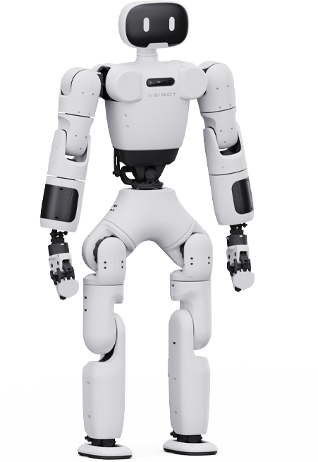
AGIBOT A2 Ultra
Full-Size Humanoid Robot
AGIBOT A2 Lite
Master of Performance
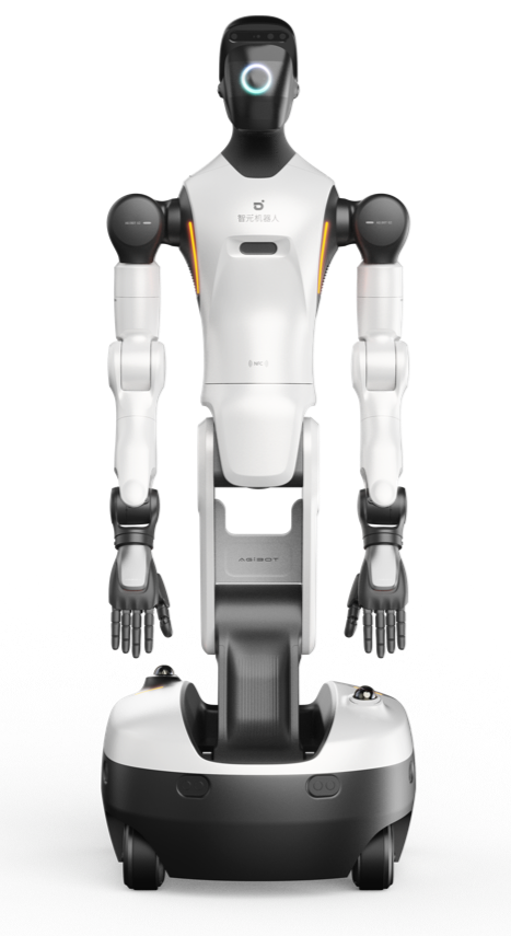
AGIBOT A2-W
Flexible Manufacturing Robot
AGIBOT X1
Full-Stack Open-Source Robot
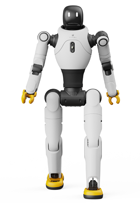
AGIBOT X2 series
Fully Intelligent & Agile Robot
AGIBOT G2
Universal Embodied Intelligent Robot
AGIBOT G1
Universal Embodied Intelligent Robot
One-stop Development Platform for Embodied AI
Integrated Data-solution for Embodied Al
Data Service
D1 Pro/Edu
All-round Quadruped Intelligence Pioneer
D1 Ultra
Quadruped Intelligent Robot
D1 Max
A Productivity Platform
Built for Industry
D1 MaxPro
Meets All Industrial
Operational Demands
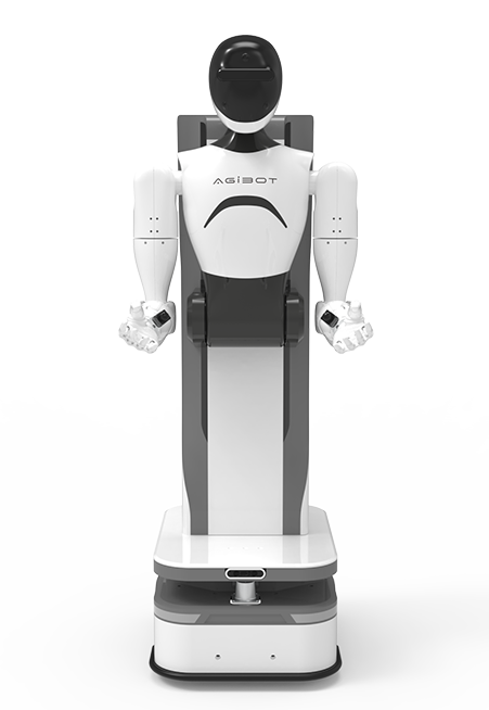
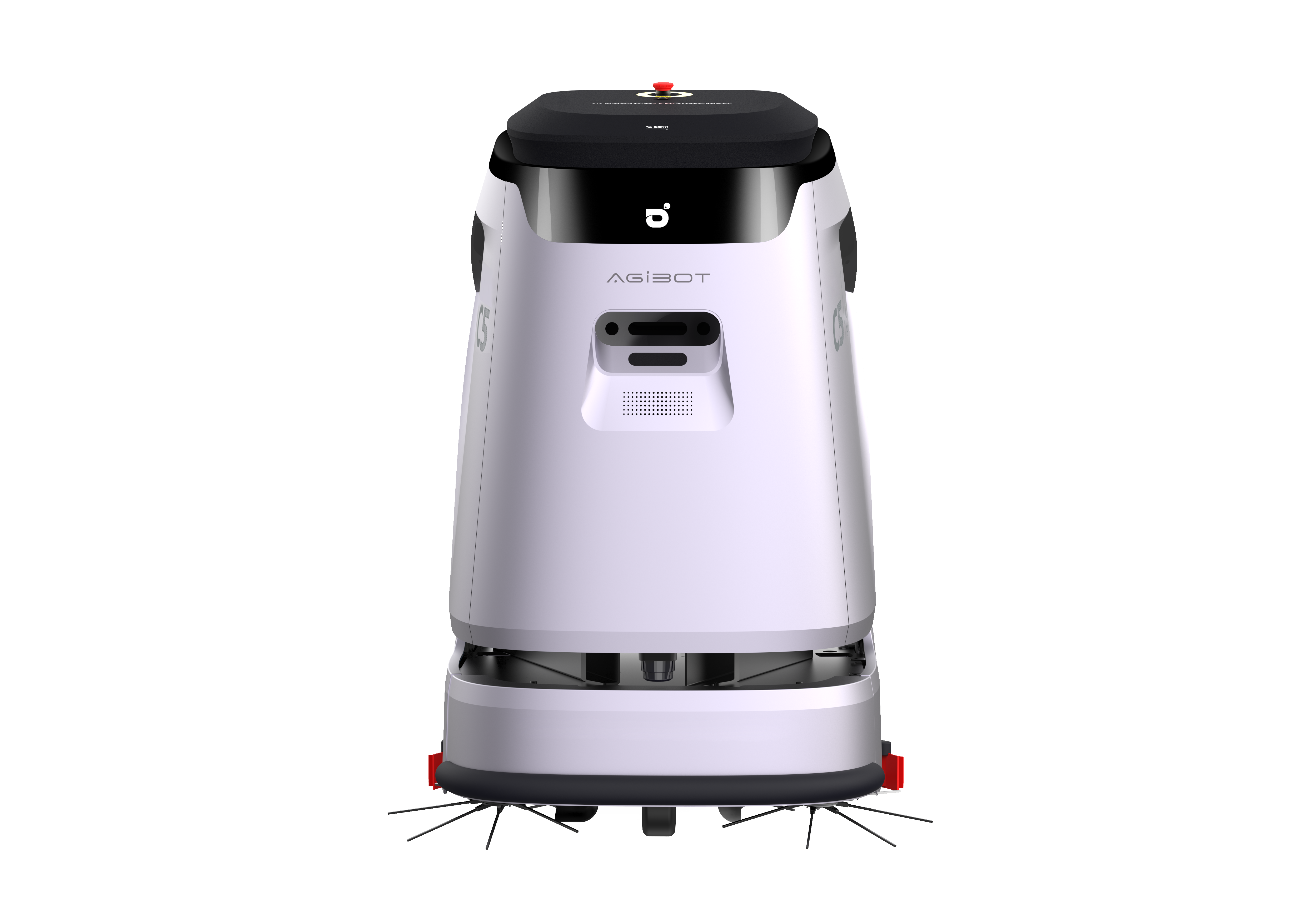
AGIBOT C5
AGIBOT's First Commercial Cleaning Robot
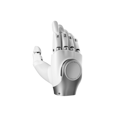
OmniHand 2025
Small Form Factor, Seamless Compatibility
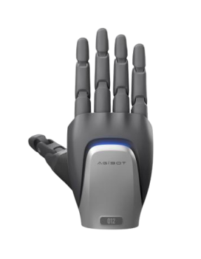
OmniHand pro 2025
Enhanced Perception, More Capabilities
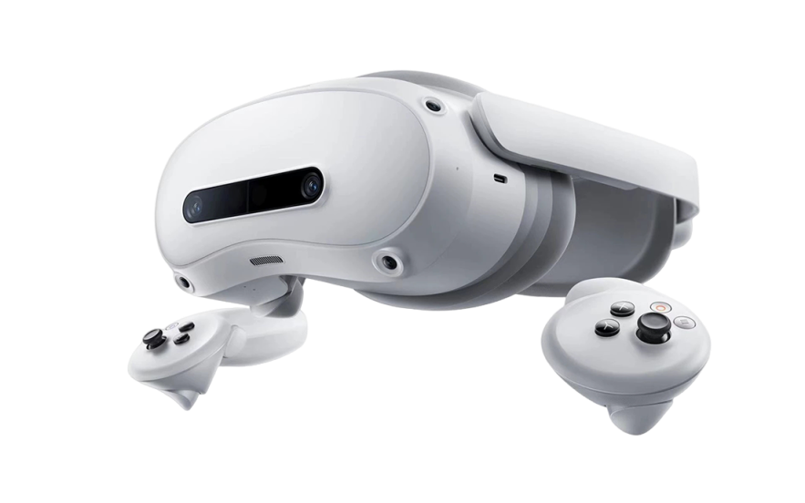
VR Teleoperation Kit
Compatible only with AGIBOT A2
Xia Lan
Store
Research
Open Source
AGIBOT World Dataset
AGIBOT X1
AimRT Framework
Open Source Doc
News Center
News and Information
Marketing Events
About Us
Contact Us
APP
CN
EN
JP
Menu
Home page
Products
AGIBOT A2
A2 Ultra
A2 Lite
A2-W
AGIBOT X
X1
X2
AGIBOT Genie
G2
G1
Data Service
AGIBOT D1
D1 Pro/Edu
D1 Ultra
D1 Max
D1 MaxPro
AGIBOT C5
C5
AGIBOT Accessories
OmniHand 2025
OmniHand pro 2025
VR
AGIBOT Premium Selection
Xia Lan
Document Center
Store
Research
Open Source
AGIBOT World Dataset
AGIBOT X1
AimRT Framework
News Center
News and Information
Marketing Events
About Us
Contact Us
APP
EN
CN
JP